Garmin GLS 10 Sonar Module Installation Instructions
Garmin GLS 10 Sonar Module Manual
 |
View all Garmin GLS 10 Sonar Module manuals
Add to My Manuals
Save this manual to your list of manuals |
Garmin GLS 10 Sonar Module manual content summary:
- Garmin GLS 10 Sonar Module | Installation Instructions - Page 1
Garmin® device according to these instructions. Read all installation instructions before proceeding with the installation. If you experience difficulty during the installation, go to support.garmin should mount the sonar module in a location where create a service loop at least 25 cm (10 in.) long - Garmin GLS 10 Sonar Module | Installation Instructions - Page 2
over the rotating joint. The loop must be large enough to allow full rotation of the transducer in both directions. Allow a minimum of 25 cm (10 in.) of cable to cover the 20 cm (8 in.) section between mounting points. 2 Using the included hex wrench, attach the bracket to the transducer with - Garmin GLS 10 Sonar Module | Installation Instructions - Page 3
location. 4 Route the transducer cable to the installation location of the sonar module while taking these precautions. • You should not route the cable close connect an optional extension cable, available at buy.garmin.com or from your Garmin dealer. 5 Position the transducer to your desired angle - Garmin GLS 10 Sonar Module | Installation Instructions - Page 4
-11). Go to buy.garmin.com or contact your Garmin dealer for information. Installing completely through the transom. 10Route the transducer cable to the sonar module: • If you are routing the cable using a pass- sources of electrical interference. Mounting the GLS 10 Black Box Device NOTICE If you - Garmin GLS 10 Sonar Module | Installation Instructions - Page 5
the device to the mounting location. Installation Diagram Compatible Garmin chartplotter Panoptix LiveScope GLS 10 sonar module Garmin Marine Network small connector to full-size GarminMarine Network adapter cable RJ-45 connector Garmin Marine Network cable small connector to NETWORK port Water - Garmin GLS 10 Sonar Module | Installation Instructions - Page 6
Panoptix LiveScope GLS 10 Sonar Module Specifications Dimensions (W x H x D) 245 x 149 x 65 mm (9.7 x 5.9 x 2.6 in.) Weight 1.96 kg (4.33 lbs.) Operating temperature From -15 to 70°C (from 5 to 158°F) Storage temperature From -40 to 85°C (from -40 to 185°F) Power input From 10 to 32 Vdc
-
 1
1 -
 2
2 -
 3
3 -
 4
4 -
 5
5 -
 6
6
 |
 |
PANOPTIX
™
LIVESCOPE
™
INSTALLATION
INSTRUCTIONS
Important Safety Information
WARNING
See the
Important Safety and Product Information
guide in the
chartplotter product box for product warnings and other
important information.
You are responsible for the safe and prudent operation of your
vessel. Sonar is a tool that enhances your awareness of the
water beneath your boat. It does not relieve you of the
responsibility of observing the water around your boat as you
navigate.
CAUTION
Failure to install and maintain this equipment in accordance with
these instructions could result in damage or injury.
Always wear safety goggles, ear protection, and a dust mask
when drilling, cutting, or sanding.
NOTICE
When drilling or cutting, always check what is on the opposite
side of the surface.
To obtain the best performance and to avoid damage to your
boat, you must install the Garmin
®
device according to these
instructions.
Read all installation instructions before proceeding with the
installation. If you experience difficulty during the installation, go
to
support.garmin.com
for more information.
Software Update
You must update the Garmin chartplotter software when you
install this device.
If your chartplotter has Wi
‑
Fi
®
technology, you should update the
software using the ActiveCaptain
®
app on a compatible Android
™
or Apple
®
device.
If your chartplotter does not have Wi
‑
Fi technology, you should
update the software using a memory card and a Windows
®
or
Mac
®
computer.
For more information, go to
support.garmin.com
.
Tools Needed
•
Drill
•
4 mm (
5
/
32
in.) and 3.2 mm (
1
/
8
in.) drill bits
•
Masking tape
•
#2 Phillips screwdriver
•
Marine sealant
•
32 mm (1
1
/
4
in.) hole saw (optional)
•
Cable ties (optional)
Mounting Considerations
•
You must angle the transducer correctly for your selected
mode to work properly.
•
You must install the sonar module in a location with adequate
ventilation where it will not be exposed to extreme
temperatures.
•
You should mount the transducer in a location where it will
not be jarred when launching, hauling, or storing.
•
You should mount the transducer in a location where it is not
behind strakes, struts, fittings, water intake or discharge
ports, thru-hull transducers, or anything that creates air
bubbles or causes the water to become turbulent. Turbulent
water may interfere with the sonar beam.
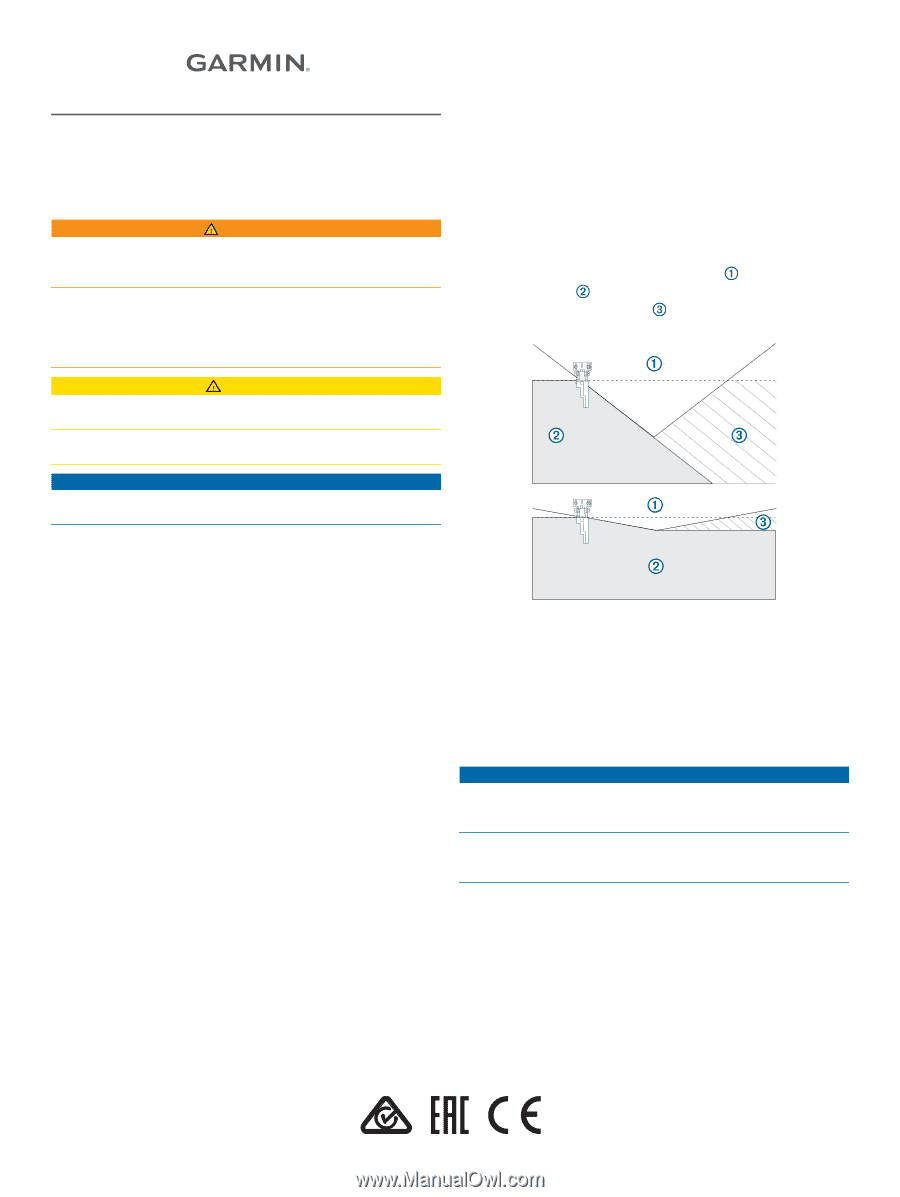
•
You should mount the transducer as close to the center line
of the boat as possible.
•
When mounted farther from the center of the transom, a
greater deadrise can cause the boat hull
to interfere with
the sonar beam
, and can cause inconsistent detection on
the opposite side of the boat
. The transducer is shown
from behind.
•
On single-drive vessels, you must not mount the transducer
in the path of the propeller.
•
On twin-drive vessels, you should mount the transducer
between the drives, if possible.
•
You should mount the sonar module in a location where the
LEDs are visible, where the cables can be connected, and
where the device will not be submerged.
Cable Considerations
NOTICE
Separating the Siamese cables near the rotating joint on a
cable-steered trolling motor reduces stress and extends the life
of the cables.
Zip ties and cable clamps can over-tighten and damage or break
the cable, or cause cable fatigue due to repeated rotation of the
motor.
You should use black electrical tape to secure the cables above
and below the rotating joint. If you secure the cables with zip
ties, do not over-tighten the zip ties.
You should secure the cables above and below the pivot joint of
your trolling motor.
You should create a service loop at least 25 cm (10 in.) long in
the cables, with the rotating joint centered on the loop.
You should use the included tool, a flathead screwdriver, or a
blunt knife to separate the cables.
GUID-8ABE5659-3192-4519-8A48-66421E004620 v4
February 2020