Garmin GLS 10 Sonar Module Installation Instructions - Page 4
Installing the Transducer on a Transom, Mounting the GLS 10 Black Box Device
 |
View all Garmin GLS 10 Sonar Module manuals
Add to My Manuals
Save this manual to your list of manuals |
Page 4 highlights
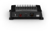
Trolling Motor Shaft Orientation The angle of installation depends on the side of the trolling motor shaft you mount the bracket on, and your desired field of view. TIP: No tools are necessary to change the orientation from forward to down. Turn the mount one click to change the orientation from forward to down. Port side, forward view Port side, downward view Starboard side, forward view Starboard side, downward view 2 Using the transom mount as a template, mark the location of the pilot holes. 3 Wrap a piece (7/10 in.) from of tape around the point of the a 4 bit, mm (5/32 in.) bit to avoid drilling at 19 mm the pilot holes too deep. 4 If you are installing the bracket on fiberglass, place a piece of tape over the pilot-hole location to reduce cracking of the gel coat. 5 U19simngmth(3e/44inm.)md(e5e/3p2 in.) bit, drill the pilot holes at the marked locations. approximately 6 Apply marine sealant to the included 20 mm screws. 7 Using the three 20 mm screws , attach the transducer mount to the transom. NOTICE When mounting the transducer, use the bottom screw hole in the middle of the mount. This is especially important on vessels that operate at high speeds. If the top hole is used, the bracket may bend or break when the vessel moves at high speeds, dislodging the transducer. Installing the Transducer on a Transom If necessary, to reduce spray from the transducer, you can install an optional heavy duty transom mount with a spray shield ( 010-12006-11). Go to buy.garmin.com or contact your Garmin dealer for information. Assembling the Transom-Mount Hardware 1 Attach the transducer mount bracket to the transducer using the mounting screws and lock washers . 2 Attach the transducer mount bracket to the transom mount bracket using the bolts , flat washers , and lock nuts . NOTE: The recommended torque applied to the screw is 15 lb-ft. (20 N-m). NOTE: If the transducer causes excessive spray when mounted to the transom, you can install a heavy duty transom mount with a spray shield (010-12006-11). Go to buy.garmin.com or contact your Garmin dealer for information. Installing the Transom-Mount Hardware NOTICE If you are mounting the bracket on fiberglass with screws, it is recommended to use a countersink bit to drill a clearance counterbore through only the top gel-coat layer. This will help to avoid cracking in the gel-coat layer when the screws are tightened. 1 Place the transducer mount so the top of the transducer is under the transom. 4 8 If you must route the cable through the transom, choose a pilot-hole location well above the waterline and mark it. 9 If you marked a pilot hole in step 8, use a 32 mm (1 1/4 in.) hole saw to drill a pass-through hole completely through the transom. 10Route the transducer cable to the sonar module: • If you are routing the cable using a pass-through hole, push it through the hole you drilled in step 9. • If you are not routing the cable using a pass-through hole, route the cable up and over the top of the transom . You should avoid routing the cable close to electrical wires or other sources of electrical interference. Mounting the GLS 10 Black Box Device NOTICE If you are mounting the device in fiberglass, when drilling the pilot holes, use a countersink bit to drill a clearance counterbore through only the top gel-coat layer. This will help to avoid cracking in the gel-coat layer when the screws are tightened. NOTE: Screws are included with the device, but they may not be suitable for the mounting surface. Before you mount the device, you must select a mounting location, and determine what screws and other mounting hardware are needed for the surface. 1 Place the black box device in the mounting location, and mark the location of the pilot holes. 2 Drill a pilot hole for one corner of the device. 3 Loosely fasten the device to the mounting surface with one corner, and examine the other three pilot-hole marks. 4 Mark new pilot-hole locations if necessary, and remove the device from the mounting surface. 5 Drill the remaining pilot holes.
-
 1
1 -
 2
2 -
 3
3 -
 4
4 -
 5
5 -
 6
6
 |
 |
