Garmin GMR 1226 xHD2 Installation Instructions - Page 4
Radar Operation
 |
View all Garmin GMR 1226 xHD2 manuals
Add to My Manuals
Save this manual to your list of manuals |
Page 4 highlights
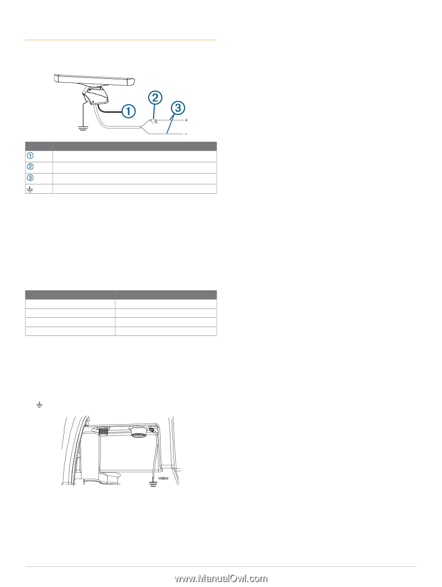
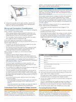
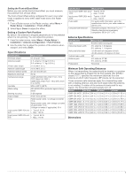
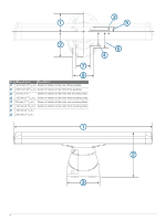
addition, connecting the power cable without the appropriate fuse in place voids the product warranty. Some radar models do not require a voltage converter unit. If your model is packaged without a voltage converter, it should be connected directly to power. Item Description To the Garmin Marine Network 15 A fuse holder To the boat battery (10 to 32 Vdc) Water ground connection 1 Route the power cable to the radar and boat battery. 2 Connect the power cable to the boat battery. 3 Connect the power cable to the POWER port on the radar. Power Cable Extensions Connecting the power cable directly to the battery is recommended. If it is necessary to extend the cable, the appropriate gauge of wire must be used for the length of the extension. You must use crimp connectors and heat-shrink to create a water-resistant connection. Distance 3 m (9 ft. 10 in.) 5 m (16 ft. 4 in.) 6.5 m (21 ft. 3 in.) 8 m (26 ft. 2 in.) Wire Gauge 3.31 mm² (12 AWG) 5.26 mm² (10 AWG) 6.63 mm² (9 AWG) 8.36 mm² (8 AWG) Grounding the Radar The radar (and voltage converter, if applicable) must be connected to the appropriate type of ground using a 3.31 mm² (12 AWG) copper wire (not included). 1 Route a 3.31 mm² (12 AWG) copper wire to a water ground location and to the radar pedestal. 2 Connect the wire to the ground connector on the pedestal ( ) using the pre-installed crimp connector. 3 Coat the ground screw and crimp connector with marine sealant. 4 Connect the other end of the wire to the water ground location on the boat, and coat the connection with marine sealant. 5 Select an option: • If your radar was not packaged with a voltage converter, no further grounding is necessary. 4 • If your radar was packaged with a voltage converter, proceed to step 6. 6 Route a different 3.31 mm² (12 AWG) copper wire to water ground location and to the voltage converter. 7 Loosen a screw on one corner of the voltage converter and secure the copper wire to the screw. 8 Coat the screw and wire on the voltage converter with marine sealant. 9 Connect the other end of the wire to the RF ground location on the boat, and coat the connection with marine sealant. Garmin Marine Network Considerations This device connects to Garmin Marine Network devices to share radar data with compatible devices on the network. When connecting to a Garmin Marine Network device, observe these considerations. • A Garmin Marine Network cable must be used for all Garmin Marine Network connections. ◦ Third-party CAT5 cable and RJ45 connectors must not be used for Garmin Marine Network connections. ◦ Additional Garmin Marine Network cables and connectors are available from your Garmin dealer. • Although it is not recommended, you can use a field- installable connector to create a custom-length Garmin Marine Network cable if necessary. Follow the directions provided with the connector. Radar Operation All functions of this radar are controlled with your Garmin chartplotter. See the Radar section of your chartplotter's owner's manual for operating instructions. To download the latest manual, go to support.garmin.com. If you have more than one radar on your boat, you must be viewing the radar screen for the radar you want to configure. Specifying the Antenna Size Before you can use the radar on your system, you must specify the antenna size. 1 Turn on the radar and all devices connected to the Garmin Marine Network. An antenna-selection prompt appears on the connected chartplotters. NOTE: If the entire system is being turned on for the first time, the antenna-selection screen is part of the initial setup process. 2 Select the installed antenna size for each open-array radar installed on the boat. TIP: If you need to specify a different antenna size, while viewing the radar screen for the radar you want to change, select Menu > Radar Setup > Installation > Antenna Configuration > Antenna Size, and select the antenna size. Front-of-Boat Offset The front-of-boat offset compensates for the physical location of the radar scanner on a boat, if the radar scanner does not align with the bow-stern axis. Measuring the Potential Front-of-Boat Offset The front-of-boat offset compensates for the physical location of the radar scanner on a boat, if the radar scanner does not align with the bow-stern axis. 1 Using a magnetic compass, take an optical bearing of a stationary target located within viewable range. 2 Measure the target bearing on the radar. 3 If the bearing deviation is more than +/- 1°, set the front-of- boat offset.
-
 1
1 -
 2
2 -
 3
3 -
 4
4 -
 5
5 -
 6
6 -
 7
7 -
 8
8
 |
 |