Garmin GMR 18 HD3 Installation Instructions - Page 7
Mounting the Radar
 |
View all Garmin GMR 18 HD3 manuals
Add to My Manuals
Save this manual to your list of manuals |
Page 7 highlights
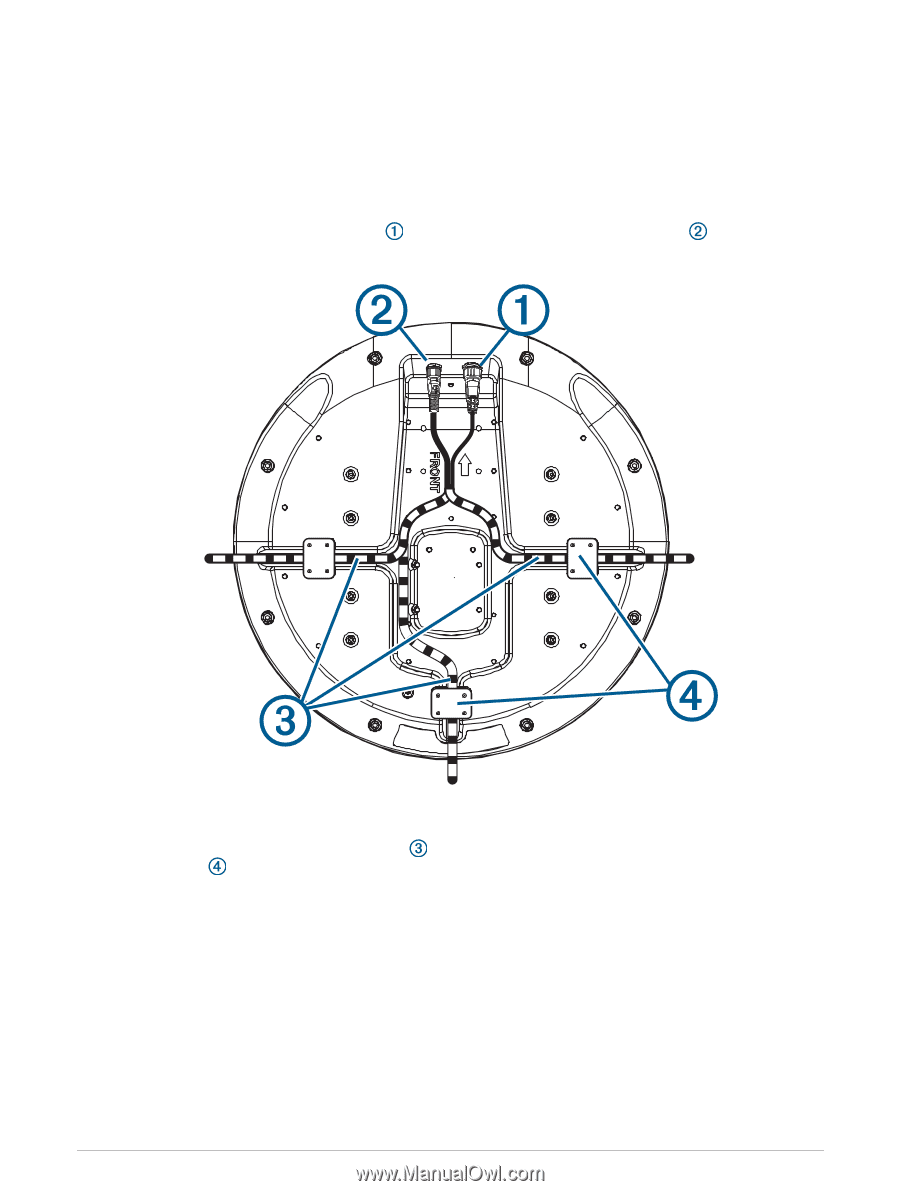
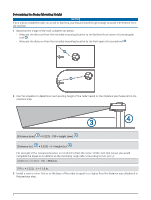
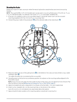
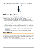
Mounting the Radar Before you mount the radar, you must review the mounting location considerations and select a mounting location. NOTE: The supplied M8 x 1.25 x 60 threaded rods can be used on mounting thicknesses of 5 to 30 mm (3/16 to 1 3/16 in.) (recommended). For surfaces over 30 mm (1 3/16 in.), use longer threaded rods. 1 If you are not installing the device on a pre-drilled Garmin compatible radar mount, use the included mounting template to drill four 9.5 mm (3/8 in.) mounting holes. 2 Connect the power cable to the power port and the network cable to the network port . 3 Press the cables into any of the guide grooves on the bottom of the case, and secure them using a cable hold-down plate . The cables should be bent or twisted as little as possible. 4 Using the arrow on the bottom as a reference, position the radome on the mounting surface aligned to the front of the vessel. NOTE: If you choose not to align the dome with the front of the vessel, you can adjust the front-of-boat offset after the dome is installed (Measuring and Setting the Front-of-Boat Offset, page 9). 5 Apply the included anti-seize compound to the threads of the four M8 x 1.25 x 60 threaded rods. 6 Insert the four threaded rods into the mounting holes on the bottom of the radome. Up to 50 mm (2 in.) of the threaded rods may extend below the radome. 7 Apply a bead of marine sealant on the mounting surface around each mounting hole. 7
-
 1
1 -
 2
2 -
 3
3 -
 4
4 -
 5
5 -
 6
6 -
 7
7 -
 8
8 -
 9
9 -
 10
10 -
 11
11 -
 12
12 -
13
-
14
 |
 |