Garmin GMR 624 xHD2 Open Array Radar and Pedestal Installation Instructions - Page 2
Mounting the Radar
 |
View all Garmin GMR 624 xHD2 Open Array Radar and Pedestal manuals
Add to My Manuals
Save this manual to your list of manuals |
Page 2 highlights
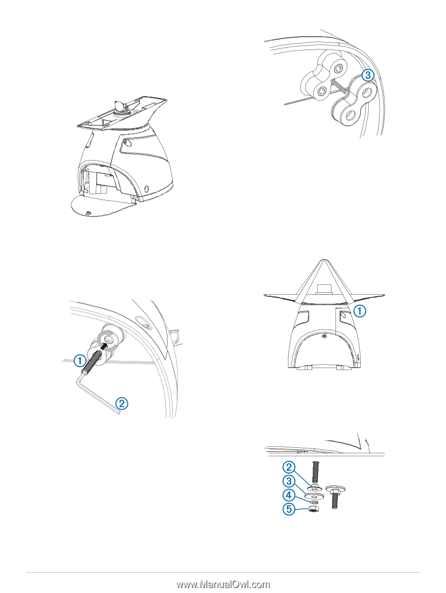
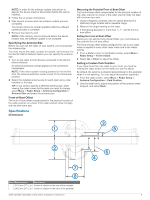
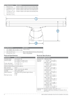
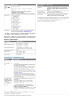
• Secure the included mounting template to the surface at the chosen mounting location, along the bow-stern axis as indicated on the template. 2 Determine which of the two mounting-hole patterns indicated on the template are appropriate for the mounting surface and drill the four mounting holes using a 15 mm (19/32 in.) drill bit. 3 Remove the hatch on the front of the pedestal by loosening the screw and lifting the hatch off of the hinges. 4 Apply the included Petrolatum Primer to one half of the threads of the four threaded rods. 5 Insert the ends of the threaded rods coated in Petrolatum Primer into the pedestal, matching the hole pattern drilled in step 2. 6 Tighten the threaded rods using a 5 mm hex wrench . À Á To avoid damaging the pedestal, you should stop tightening the threaded rods when they no longer turn easily. Mounting the Radar Before you can mount the radar, you must first select a mounting location, and prepare the mounting surface and the radar (Preparing the Surface and the Radar for Mounting, page 1). 1 Take note of which end of the pedestal you plan to mount facing the bow along the bow-stern axis. If the hatch side is facing the bow, you must adjust the frontof-boat offset on the chartplotter to receive an accurate radar reading (Front-of-Boat Offset, page 5). 2 Position the included strap over the antenna, as close to the pedestal base as possible . À 7 Install the isolators over the threaded rods, and push them  securely onto the four raised locations on the bottom of the pedestal. 3 Hoist the radar into position, and carefully lower it onto the mounting surface, feeding the threaded rods through the holes. 4 From under the mounting surface, place the shoulder washers on the threaded rods and feed them into the Á mounting surface so they fit securely. 5 Place the flat washers , lock washers , and hex nuts on Â Ã Ä the threaded rods. 6 Torque the hex nuts to 1.5 kgf-m (130 lbf-in. [11 lbf-ft.]) to securely fasten the radar to the surface without damaging the radar or the mounting hardware. 2 GMR 420/620/1220/2520 xHD2 Series Installation Instructions
-
 1
1 -
 2
2 -
 3
3 -
 4
4 -
 5
5 -
 6
6 -
 7
7 -
 8
8
 |
 |