Garmin GPSMAP 8530 Black Box Installation Instructions - Page 3
Mounting Considerations, Card Reader Mounting Considerations - testing
 |
View all Garmin GPSMAP 8530 Black Box manuals
Add to My Manuals
Save this manual to your list of manuals |
Page 3 highlights
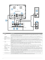
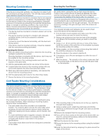
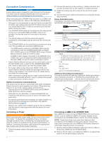
Mounting Considerations NOTICE If the device is mounted vertically, it is important to install it with the connectors pointing downward. This will help avoid potential water retention around the connectors. This device should be mounted in a location that is not exposed to extreme temperatures or conditions. The temperature range for this device is listed in the product specifications. Extended exposure to temperatures exceeding the specified temperature range, in storage or operating conditions, may cause device failure. Extreme-temperature-induced damage and related consequences are not covered by the warranty. • The device must be mounted in a location where it will not be submerged. • The device must be mounted in a location with adequate ventilation where it will not be exposed to extreme temperatures. • It is best to mount the device horizontally, with the heat sink facing upward. • If the device must be mounted vertically, it must be installed with the connectors pointing downward. Mounting the Device 1 After you select a mounting location, determine the mounting hardware needed for the surface. Mounting hardware is included with the device, but it may not be suitable for the mounting surface. 2 Place the device in the mounting location and mark the location of the pilot holes. 3 Drill the appropriate pilot hole for one corner of the device. 4 Loosely fasten the device to the mounting surface with one corner and examine the other three pilot-hole marks. 5 Mark new pilot-hole locations if necessary, and remove the device from the mounting surface. 6 Drill the appropriate pilot holes for the other three marks. 7 Secure the device to the mounting location. Mounting the Card Reader NOTICE Be careful when cutting the hole to flush mount the device. There is only a small amount of clearance between the case and the mounting holes, and cutting the hole too large could compromise the stability of the device after it is mounted. If you are mounting the bracket on fiberglass with screws, it is recommended to use a countersink bit to drill a clearance counterbore through only the top gel-coat layer. This will help to avoid any cracking in the gel-coat layer when the screws are tightened. The included template and hardware can be used to flush mount the device at the selected location. 1 Trim the flush-mount template and make sure it fits in the location where you want to mount the device. 2 Remove the protective liner from the back of the template and adhere it to the location where you want to mount the device. 3 Using a ¼ in. (6 mm) drill bit, drill one or more of the holes inside the corners of the solid line on the template to prepare the mounting surface for cutting. 4 Using a jigsaw, cut the mounting surface along the inside of the solid line indicated on the template. 5 Place the device in the cutout to test the fit. 6 If necessary, use a file and sandpaper to refine the size of the cutout. 7 After the device fits correctly in the cutout, make sure that À the mounting holes on the device line up with the pilot holes on the template. Á Card Reader Mounting Considerations NOTICE This device should be mounted in a location that is not exposed to extreme temperatures or conditions. The temperature range for this device is listed in the product specifications. Extended exposure to temperatures exceeding the specified temperature range, in storage or operating conditions, may cause device failure. Extreme-temperature-induced damage and related consequences are not covered by the warranty. The card reader can be flush mounted in the dashboard using the included hardware. When selecting a mounting location, observe these considerations. • The card reader should be mounted in an accessible location. You must be able to access the card reader when necessary to insert and remove memory cards containing additional mapping and device updates, and to transfer user data. • To avoid interference with a magnetic compass, the device should not be installed closer to a compass than the compass-safe distance value listed in the product specifications. • The location must allow room for the routing and connection of the cables. 8 If the mounting holes on the device do not line up, mark the new pilot-hole locations. 9 Using a center punch, indent the pilot holes and drill the clearance counterbore through the gell-coat layer as advised in the notice. 10 Remove the template from the mounting surface. 11If you will not have access to the back of the device after you mount it, connect all necessary cables to the device before placing it into the cutout. 12 Place the device into the cutout. 13Secure the device to the mounting surface using the included screws . Â 14Install the decorative bezel by snapping it in place around the edges of the device. 3
-
 1
1 -
 2
2 -
 3
3 -
 4
4 -
 5
5 -
 6
6 -
 7
7 -
 8
8 -
 9
9 -
10
-
11
-
12
 |
 |
