Garmin GRA 55 Maintenance Manual - Page 34
Removal And Replacement Information
 |
View all Garmin GRA 55 manuals
Add to My Manuals
Save this manual to your list of manuals |
Page 34 highlights
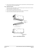
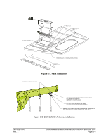
6 REMOVAL AND REPLACEMENT INFORMATION 6.1 Unit Installation 6.1.1 Installation Procedure 1. Place the unit on the mounting rack, ensuring the GRA 55/5500 rear feet are aligned in the mounting rack slots. 2. Slide the GRA 55/5500 back until the feet are fully engaged with the mounting rack. 3. Lift the lockdown collar in place on the GRA 55/5500 hook and hand turn the lockdown mechanism knob clockwise until the GRA 55/5500 is secure and the knob cannot reasonably be ratcheted any tighter by hand. 6.1.2 Removal Procedure 1. Pull back on the lockdown mechanism and simultaneously turn counterclockwise until free. 2. Disengage the lockdown mechanism collar from the GRA 55/5500 hook and slide the GRA 55/5500 forward to remove from the mounting rack. 6.2 Rack Installation The GRA 55/5500 mounting surface should be capable of providing a sufficient electrical bond to the aircraft to minimize Electromagnetic Interference (EMI) and provide protection from High-Intensity Radiation Fields (HIRF). Bonding resistance measured between the GRA 55/5500 mounting rack and the airframe must measure less than 2.5 milliohms. 6.2.1 Installation Procedure 1. Clean and inspect the mounting surface of the rack mount. Ensure the bonding surface is adequate to meet the required resistance measurement of 2.5 milliohms. 2. Place the rack on the mounting shelf assembly with lockdown knob facing forward. 3. Install and secure mount rack with 4 ea. screw (see Table A-1for rack fasteners). Torque 20-25 in lbs. 4. Perform bond resistance measurement. Value should be less than 2.5 milliohms. 6.2.2 Removal Procedure 1. Remove GRA 55/5500 unit if not already done. 2. Remove 4 ea. screw (see Table A-1for rack fasteners). 3. Remove mounting rack. 6.3 Antenna Installation 6.3.1 Installation Procedure 1. Clean and inspect the antenna mount. Remove debris and excess sealant if replacing existing antenna. 2. Apply the conductive gasket on the underside of the antenna using the fastener holes as guides. 3. Use MS24693-C272 stainless steel countersunk head machine screws (No. 10, supplied) to secure antennas. Verify that directional arrow on the antenna is pointed towards the front of the helicopter. 4. Torque antenna fasteners in a star pattern to 20-25 in lbs. Torque should be applied evenly across all fasteners to avoid deformation of the mounting area. 5. Ensure that the antenna base and antenna mount are in continuous contact with the gasket. 190-01277-A3 Rev. 1 System Maintenance Manual GRA 55/5500 Bell 206 STC Page 6-1
-
 1
1 -
2
-
3
-
4
-
5
-
6
-
7
-
8
-
9
-
10
-
11
-
12
-
13
-
14
-
15
-
16
-
17
-
18
-
19
-
20
-
21
-
22
-
23
-
24
-
25
-
26
-
27
-
28
-
 29
29 -
 30
30 -
 31
31 -
 32
32 -
 33
33 -
 34
34 -
 35
35 -
 36
36 -
 37
37 -
 38
38 -
 39
39 -
40
-
41
-
42
-
43
-
44
-
45
-
46
-
47
-
48
 |
 |
