Garmin GSD 24 GSD 24 Transducer Adapter Installation Instructions - Page 1
Garmin GSD 24 Manual
 |
View all Garmin GSD 24 manuals
Add to My Manuals
Save this manual to your list of manuals |
Page 1 highlights
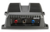
GSD 24 Transducer Adapter Installation Instructions About the GSD 24 Transducer Adapter WARNING See the Important Safety and Product Information guide in the GPS device product box for product warnings and other important information. NOTICE The GSD 24 adapter is not meant for use with a Garmin differential 8-pin transducer. Do not cut a Garmin differential 8-pin transducer; instead, plug it directly into the GSD 24 according to the GSD 24 Installation Instructions. Use this adapter to connect a non-differential transducer, such as a legacy Garmin/Airmar® 6-pin transducer, to a GSD™ 24 sounder. In order to adapt a non-differential transducer for use with a Garmin differential sounder, you must cut the connector from your existing non-differential transducer and connect the wires to the wire block inside the GSD 24 Transducer Adapter by following these instructions. Tools Needed • Drill and 1/8 in. (3.2 mm) drill bit • #2 Phillips screwdriver • 3 mm flat screwdriver • Cable ties (optional) • Wire cutter • Wire stripper • /13 16 in. (21 mm) wrench Mounting the Adapter Selecting a Mounting Location Consider the following conditions when choosing a location to mount the GSD 24 Transducer Adapter. • The adapter cable should easily reach the transducer connector on the GSD 24 when mounted. The adapter cable length is 24 in. (60.1 cm). • The adapter should not be installed in a location where it is submerged in water. • The adapter should be located at least 6 in. (15.25 cm) from electrical interference such as a motor. • If there is not a mounting surface suitable for using the included screws, the adapter can be secured to a structure using cable ties (not included). Fastening the Adapter to the Mounting Location 1. Use the included template (page 19) to mark the pilot-hole locations. 2. Drill the two pilot holes with a 1/8 in. (3.2 mm) drill bit. 3. Install the included screws in the pilot holes, but do not tighten them flush with the surface. 4. Place the GSD 24 adapter on the screws and slide it in place. 5. Tighten the screws until the device is securely fastened to the surface. NOTE: You may find it easier to connect the wires with the GSD 24 adapter unmounted, and then complete the mounting process. Connecting a Legacy Transducer to the Adapter NOTICE The GSD 24 adapter is not meant for use with a Garmin differential 8-pin transducer. Do not cut a Garmin differential 8-pin transducer; instead, plug it directly into the GSD 24 according to the GSD 24 Installation Instructions. Preparing the Legacy Transducer 1. Cut the connector from a non-differential transducer ➊, as close to the connector as possible. ➋ ➊ ➌ ➍ 2. Feed the cut end of the cable through the nut ➋ on the side of the housing and pull it through the other side. Do not tighten the nut at this time. 3. Use the wire stripper to remove about 3 1/2 in. (90 mm) of the outer cable jacket ➌ and foil shield. 4. Use the wire stripper to remove about 1/4 in. (6 mm) of the insulation from each internal wire ➍. Tinning each of the stripped wires is recommended, but not necessary. Connecting the Legacy Transducer Wires Connect the wires to the wire block in the adapter using a 3 mm flat screwdriver. Consult the wiring table when connecting the wires. Specific examples of many Garmin/Airmar transducer wire colors are provided on page 2. Wire Block Wire Function Number 1 Depth + 2 Depth - 3 Shield 4 Ground 5 Temp* 6 XID 7 Speed power 8 Speed data *If your transducer does not have temperature capability, you must install a jumper between connectors 4 and 5 on the wire block. Finalizing the Connection 1. After all the wire connections are secure, use a /13 16 in. (21 mm) wrench to tighten the nut around the transducer cable. When tightened correctly you will not be able to pull the transducer cable out of the housing. 2. Place the lid on the adapter and secure it with the four captive Phillips screws.
-
 1
1 -
 2
2 -
 3
3 -
 4
4 -
 5
5 -
 6
6 -
 7
7 -
8
-
9
-
10
-
11
-
12
-
13
-
14
-
15
-
16
-
17
-
18
-
19
-
20
 |
 |
