Garmin GSD 25 Premium Sonar Module Installation Instructions - Page 2
Cable Routing Grommets, Installation Diagram, Blink Codes, Specifications
 |
View all Garmin GSD 25 Premium Sonar Module manuals
Add to My Manuals
Save this manual to your list of manuals |
Page 2 highlights
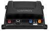
2 Install the locking rings on the marine network and power cables. 3 Connect the bare-wire end of the power cable to a 12 Vdc power source and to ground. 4 Align the notch on the end of the power cable with the power port on the device, and press the cable into place. 5 Tighten the locking ring. 6 Select an option: • If your boat is equipped with a GMS™ 10 network port expander, connect the network cable to an available port on the GMS 10. • If your boat is not equipped with a GMS 10 network port expander, connect the network cable directly to the network port on your chartplotter. Cable Routing Grommets When routing cables through your boat, it may be necessary to drill holes to route the cables. Cable routing grommets can be used to cover cable installation holes. The grommets do not create a waterproof seal. If necessary, apply a marine sealant after installation to weatherproof around the grommet and the cable. You can purchase grommets from your Garmin dealer or directly from Garmin at www.garmin.com. Installation Diagram You can use this diagram to identify the connection points from your sounder to the network, power, and transducer. Item À Á Â Ã Description Chartplotter GSD 25 Power Source Transducer Blink Codes After the sounder is installed, it turns on when the chartplotter is turned on. The two-color (green and red) status LED on the sounder indicates its operational status. LED Color Green Red Red/ Green Red Red State Slow blink Slow blink Slow blink Rapid blink sequence Solid Status The sounder is connected to a chartplotter and is operating properly. You should see sonar data on the chartplotter. The sounder is turned on, but is not connected to a chartplotter, or is waiting to connect to a chartplotter. If the sounder is connected to the chartplotter and this code persists, check the wiring connections. The sounder is in test mode. System error. The chartplotter displays a message indicating the type of failure. When the error condition is fixed, the sounder must be completely disconnected from and reconnected to its power source to clear the error. The sounder has a hardware failure. Contact Garmin Product Support for assistance. Specifications Specification Size Weight Case material Water rating* Temperature range Power input Power usage Fuse Compass safe distance Transmit power (RMS)** Frequency Depth*** Data output Measurement W × H × D: 251 x 66 x 192 mm (9. 9 x 2. 6 x 7. 6 in. ) 771 g (1. 7 lb. ) Fully gasketed, polycarbonate plastic IEC 60529 IPX7 From -15° to 70°C (from 5° to 158°F) From 10 to 35 Vdc 27 W maximum 4. 0 A 30 cm (11. 8 in. ) 1 kW Traditional sonar: 50/77/83 kHz Single channel and dual channel CHIRP: 40 kHz to 250 kHz SideVü/DownVü: CHIRP 455/800 kHz and 260/455 kHz Traditional: 1524 m (5000 ft. ); DownVü: 305 m (1000 ft. ); SideVü: 229 m (750 ft. ) left and right. Garmin Marine Network *The device withstands incidental exposure to water of up to 1 m for up to 30 min. For more information, go to www.garmin.com / waterrating. **Dependent upon transducer rating and depth ***Maximum depth, dependent upon transducer, water salinity, bottom type, and other water conditions. Garmin® and the Garmin logo are trademarks of Garmin Ltd. or its subsidiaries, registered in the USA and other countries. GSD™ is a trademark of Garmin Ltd. or its subsidiaries. These trademarks may not be used without the express permission of Garmin. © 2014 Garmin Ltd. or its subsidiaries www.garmin.com/support
-
 1
1 -
 2
2
 |
 |
