Garmin GT20-TM ndash; Transom or Trolling Motor Mount DownVuuml; 500 W CHIRP 455 - Page 2
Installing the Transducer on a Transom
Page 2 highlights
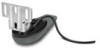
2 Secure the mount to the bracket Å with the included 12 mm M4 screws Æ, M4 flat washers Ç, and M4 lock nuts È. NOTE: You can use the 7 mm wrench to hold the lock nut in place while you tighten each 12 mm M4 screw. Installing the Transducer on a Transom Mounting Location Considerations • The transducer should be mounted as close to the center of the boat as possible. • The transducer should not be mounted behind strakes, struts, fittings, water intake or discharge ports, or anything that creates air bubbles or causes the water to become turbulent. The transducer must be in clean (non-turbulent) water for optimal performance. • The transducer should not be mounted in a location where it might be jarred when launching, hauling, or storing. • On single-drive boats, the transducer must not be mounted in the path of the propeller. The transducer can cause cavitation that can degrade the performance of the boat and damage the propeller. • On twin-drive boats, the transducer should be mounted between the drives, if possible. Installing the Transom-Mount Hardware NOTICE If you are mounting the bracket on fiberglass with screws, it is recommended to use a countersink bit to drill a clearance counterbore through only the top gel-coat layer. This will help to avoid any cracking in the gel-coat layer when the screws are tightened. Do not cut the transducer cable. Cutting the transducer cable will void your warranty. 1 Position the transducer mount À at the mounting location on the transom. 5 aUspipnrgo xtihmea t e4l ym m1 5( 5m/3m2 (in1.9 /)3 2b iitn, .d r)i ldl etehpe paitl otth heo lmeasrked locations. 6 Apply marine sealant to the included 20 mm screws, and loosely attach the transducer assembly to the transom. 7 Adjust the transducer assembly so it extends beyond the bfiobtetorgmlaosfs thhuelltrsa nors o1m0 mÂm a(p3p/8r oixn.i m)a toen layl u3m inmumm (hu1l/8l si.n . ) on 8 Make sure the transducer is aligned parallel to the water line. 9 If you need to route the cable through the transom, choose a pilot-hole location well above the waterline à and mark it. 10Place a cable clamp on the transducer cable Ä, approximately one third of the distance between the transducer and the top of the transom or the pilot hole. 11Mark the pilot-hole location for the cable clamp, and using a 3(3./ 82 inm.m ) (d1e/e8p .i n. ) bit, drill a pilot hole approximately 10 mm 12 Apply marine sealant to the included 12 mm screw, and attach the cable clamp to the transom. 13Repeat steps 10-12 to install the other cable clamp approximately two thirds of the distance between the transducer and the top of the transom or the pilot hole. 14If you marked a pilot hole in step 9, choose the appropriate drill bit to drill a pass-through hole completely through the transom: • If you have the 4-pin cable, use a 16 mm (5/8 in. ) drill bit. • If you have the 8-pin cable, use a 25 mm (1 in. ) drill bit. 15Route the transducer cable to the sounder: • If you are routing the cable using a pass-through hole, feed it through the hole you drilled in step 14, and install the cable-entry cover Ã. • If you are not routing the cable using a pass-through hole, route the cable up and over the top of the transom Å. Avoid routing the cable close to electrical wires or other sources of electrical interference. Installing the Cable-Entry Cover If you routed the cable through the transom after you installed the transducer, you should install the cable-entry cover to keep water from entering your boat. 1 Place the cable-entry cover À over the hole and the cable, with the opening pointing downward, and mark the location of the two pilot holes. 2 Align the transducer parallel to the water line Á, and mark the center location of the two outer holes and a center hole on the transducer mount. 3 (W1r9a/p32 ai np.i )e cfer oom ft htea ppoei natr oofu ntdh e ab i4t , mtmo (a5v/o3i2d idnri.l l)i nbgi tt haet p1i5l omtm holes too deep. 4 If you are installing the bracket on fiberglass, place a piece of tape over the pilot-hole location to reduce cracking of the gelcoat. 2 bRietm,o vder itlhle tchea bpliel-oetn throyl ecs oavpeprr,o xainmda,t eulys i1n0g mam 3(.3 /82 imn.m )( 1de/e8p .i n. ) 3 Fill the pass-through hole with marine sealant so it covers the cable completely and there is excess sealant around the hole and the cable. 4 Place the cable-entry cover over the hole and the cable, with the opening pointing downward. 5 Apply marine sealant to the included 12 mm M4 screws, and attach the cable-entry cover to the transom. 6 Wipe away all excess marine sealant. 2
-
 1
1 -
 2
2 -
 3
3 -
 4
4
 |
 |
