Garmin LiveScope LVS32-IF Installation Instructions - Page 12
Transducer Settings and Operation
 |
View all Garmin LiveScope LVS32-IF manuals
Add to My Manuals
Save this manual to your list of manuals |
Page 12 highlights
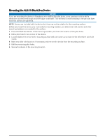
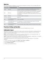
Blink Codes After the sonar module is installed, it turns on when the chartplotter is turned on. The color status LED on the sonar module indicates its operational status. LED Color State Status Green Blinking The sonar module is connected to a chartplotter and is operating properly. You should see sonar data on the chartplotter. Red Blinking The sonar module is turned on, but is not connected to a chartplotter, or is waiting to connect to a chartplotter. If the sonar module is connected to the chartplotter and this code persists, check the wiring connections. Orange Blinking A software update is in progress. Red/Green Blinking Reserved Red Two blinks followed by a 3-second pause Other sonar failure. Red Three blinks followed by a The transducer is not detected by the sonar module. If this code 3-second pause persists, check the wiring connections. Red Five blinks followed by a 3-second pause The sonar module input voltage exceeds the maximum input voltage. Transducer Settings and Operation For transducer settings and operation information, see your chartplotter owner's manual. Calibrating the Compass Before you can calibrate the compass, the transducer must be installed on the shaft far enough away from the trolling motor to avoid magnetic interference, and deployed in the water. Calibration must be of sufficient quality to enable the internal compass. NOTE: To use the compass, you must mount the transducer on the transom or the trolling motor shaft. The compass may not work when you mount the transducer on the motor. NOTE: For best results, you should use a heading sensor such as the SteadyCast™ heading sensor. The heading sensor shows the direction the transducer is pointing relative to the boat. You can begin turning your boat before calibrating, but you must fully rotate your boat 1.5 times during calibration. 1 From an applicable sonar view, select MENU > Sonar Setup > Installation. 2 If necessary, select Use AHRS to turn on the AHRS sensor. 3 Select Calibrate Compass. 4 Follow the on-screen instructions. 12
-
 1
1 -
2
-
3
-
4
-
5
-
6
-
 7
7 -
 8
8 -
 9
9 -
 10
10 -
 11
11 -
 12
12 -
 13
13 -
 14
14
 |
 |