Garmin Reactor 40 Kicker Autopilot Installation Instructions
Garmin Reactor 40 Kicker Autopilot Manual
 |
View all Garmin Reactor 40 Kicker Autopilot manuals
Add to My Manuals
Save this manual to your list of manuals |
Garmin Reactor 40 Kicker Autopilot manual content summary:
- Garmin Reactor 40 Kicker Autopilot | Installation Instructions - Page 1
REACTOR™ 40 KICKER INSTALLATION INSTRUCTIONS Important Safety Information WARNING See the Important Safety and Product Information guide in the product box for product warnings and other important information. You are responsible for the safe and prudent operation of your vessel. The autopilot is a - Garmin Reactor 40 Kicker Autopilot | Installation Instructions - Page 2
installation instructions Reactor 40 Kicker autopilot from your local Garmin dealer or at www.garmin.com. ◦ This autopilot system on a boat in salt water, you should review the saltwater considerations before installing the steering actuator (Saltwater Considerations, page 3). • You can install - Garmin Reactor 40 Kicker Autopilot | Installation Instructions - Page 3
autopilot packages. If you install the autopilot without a dedicated helm control, the autopilot CCU must be connected to the same NMEA 2000 network as a compatible Garmin chartplotter to configure and control the autopilot system. Detailed mounting instructions connect it through a 40 A fuse. If you - Garmin Reactor 40 Kicker Autopilot | Installation Instructions - Page 4
. If your motor has a tiller lock, you should remove it before installing the steering actuator. 1 Determine if your motor has a tiller lock. 2 If necessary, see your motor manual or contact the manufacturer for instructions on removing the tiller lock. Preparing the Tilt Tube 1 Locate the tilt - Garmin Reactor 40 Kicker Autopilot | Installation Instructions - Page 5
Bracket and Steering Linkage After you have installed the steering actuator in the tilt tube, you must install one of the provided motor brackets on the Kicker motor tiller arm and connect it to the steering actuator using the a linkage arm. 1 Review the table to determine which type of bracket - Garmin Reactor 40 Kicker Autopilot | Installation Instructions - Page 6
the linkage arm to your kicker motor tiller arm using the Installing the Throttle Actuator Follow the throttle actuator installation instructions Manuals on the product page for your device at www.garmin.com. Building a Basic NMEA 2000 Network for the Autopilot System NOTICE If you are installing - Garmin Reactor 40 Kicker Autopilot | Installation Instructions - Page 7
autopilot packages. If you install the autopilot without a dedicated helm control, the autopilot CCU must be connected to the same NMEA 2000 network as a compatible Garmin chartplotter to configure and control the autopilot the instructions provided with the device. Configuration The autopilot must - Garmin Reactor 40 Kicker Autopilot | Installation Instructions - Page 8
autopilot system must be connected to a compatible Garmin chartplotter on the same NMEA 2000 network as the CCU. See the installation instructions 's manual for more information. • See the chartplotter owner's manual for a list of the approved NMEA 0183 sentences that the chartplotter supports. - Garmin Reactor 40 Kicker Autopilot | Installation Instructions - Page 9
heat sink IEC 60529 IPX7* 2.7 m (9 ft.) From 11.5 to 30 Vdc 40 A, blade-type 1 A (not including the drive actuator) NMEA 2000 network (provides to 30 min. For more information, go to www.garmin.com /waterrating. The device withstands incidental exposure to water of up to 1 m for - Garmin Reactor 40 Kicker Autopilot | Installation Instructions - Page 10
the ECU has timed or chartplotter out. beeps, and the autopilot transitions to standby. Contacting Garmin Support • Go to support.garmin.com for help and information, such as product manuals, frequently asked questions, videos, and customer support. • In the USA, call 913-397-8200 or 1-800-800
-
 1
1 -
 2
2 -
 3
3 -
 4
4 -
 5
5 -
 6
6 -
 7
7 -
8
-
9
-
10
 |
 |
REACTOR
™
40
KICKER
INSTALLATION
INSTRUCTIONS
Important Safety Information
WARNING
See the
Important Safety and Product Information
guide in the
product box for product warnings and other important
information.
You are responsible for the safe and prudent operation of your
vessel. The autopilot is a tool that enhances your capability to
operate your boat. It does not relieve you of the responsibility of
safely operating your boat. Avoid navigational hazards and
never leave the helm unattended.
Always be prepared to promptly regain manual control of your
boat.
If your motor features a kill switch, you should know how to
operate it in case of an emergency. If your motor does not
feature a kill switch, you should install one before installing the
autopilot system.
Learn to operate the autopilot on calm and hazard-free open
water.
Use caution when operating the autopilot near hazards in the
water, such as docks, pilings, and other boats.
CAUTION
When in use, beware of hot surfaces on the heat-sink, motor,
and solenoid components.
When in use, beware the risk of entrapment or pinching from
moving parts.
Failure to install and maintain this equipment in accordance with
these instructions could result in damage or injury.
Installation Preparation
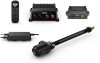
The autopilot system consists of multiple components. You
should familiarize yourself with all of the component mounting
and connection considerations before beginning installation. You
must know how the components operate together in order to
correctly plan the installation on your boat.
You can consult the layout diagrams to help understand the
mounting and connection considerations.
You should lay out all of the components on the boat as you
plan the installation to make sure your cables will reach each
component. If needed, extension cables (sold separately) for
various components are available from your Garmin
®
dealer or
from
www.garmin.com
.
You should record the serial number of each component for
registration and warranty purposes.
Tools and Supplies Needed
•
Safety glasses
•
Drill and drill bits
•
Wrenches
•
90 mm (3.5 in.) hole saw or a rotary cutting tool (for installing
an optional helm control)
•
Wire cutters/strippers
•
Phillips and flat screwdrivers
•
Cable ties
•
Waterproof wire connectors (wire nuts) or heat-shrink tubing
and a heat gun
•
Dielectric grease
•
Marine sealant
•
Portable or handheld compass (to test for magnetic
interference)
•
White lithium grease
•
Stainless steel tilt tube (recommended for saltwater
installations)
•
Thin cloth or small sponge (for cleaning the inside of the tilt
tube)
NOTE:
Mounting screws are provided for the main components
of the autopilot system. If the provided screws are not
appropriate for the mounting surface, you must provide the
correct types of screws.
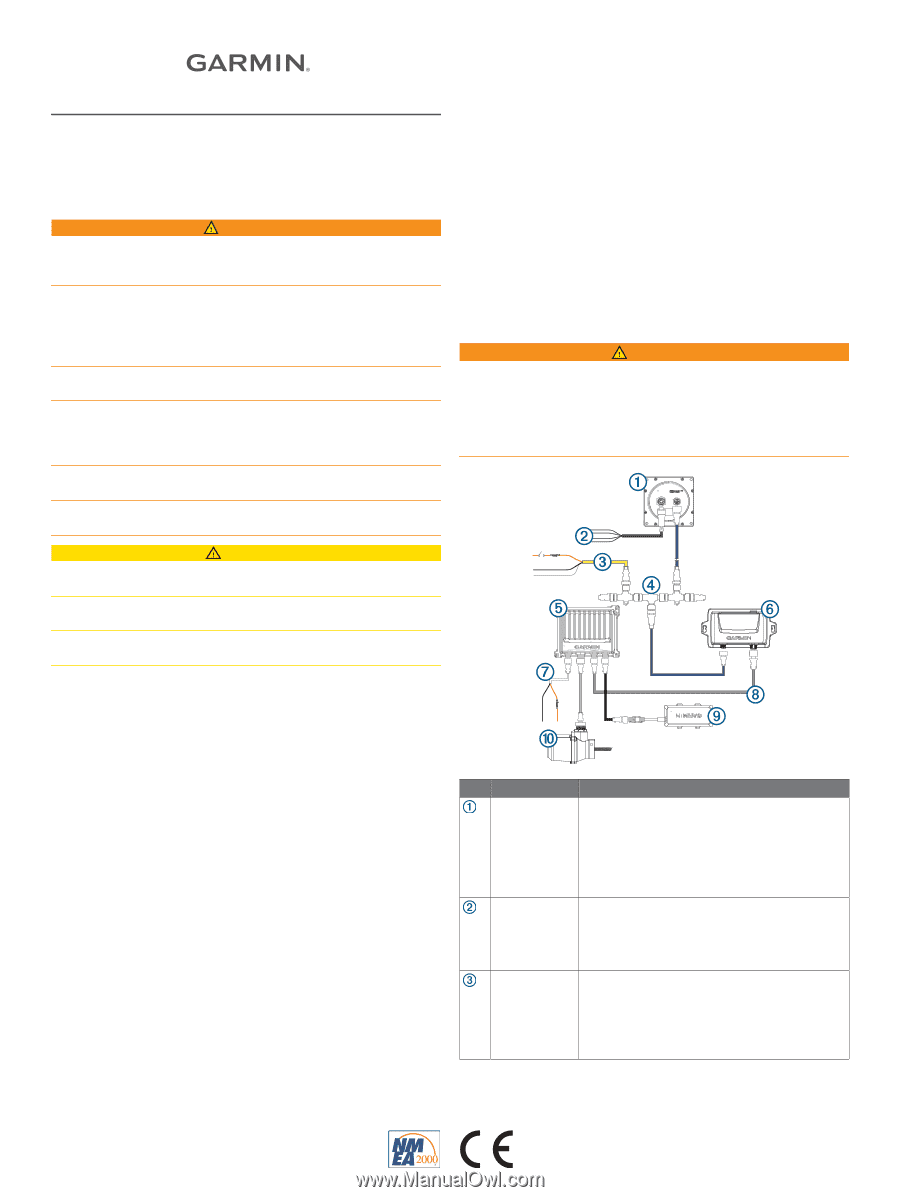
Power and Data Layout
WARNING
When connecting the power cable, do not remove the in-line
fuse holder. To prevent the possibility of injury or product
damage caused by fire or overheating, the appropriate fuse
must be in place as indicated in the product specifications. In
addition, connecting the power cable without the appropriate
fuse in place voids the product warranty.
Item
Description
Important Considerations
Helm control
A dedicated helm control is not included in all
autopilot packages. If you install the autopilot
without a dedicated helm control, the autopilot
CCU must be connected to the same NMEA
2000
®
network as a compatible Garmin
chartplotter to configure and control the autopilot
system.
Helm control
data cable
You should install this cable only if you are
connecting the autopilot to optional NMEA
®
0183
devices, such as a wind sensor, a water-speed
sensor, or a GPS device (
NMEA 0183
Connection Considerations
, page 8
).
NMEA 2000
power cable
You should install this cable only if you are
building a NMEA 2000 network. Do not install
this cable if there is an existing NMEA 2000
network on your boat.
You must connect the NMEA 2000 power cable
to a 9 to 16 Vdc power source.
October 2019
190-02451-91_0B