Garmin Reactor 40 Kicker Autopilot Installation Instructions - Page 2
Mounting and Connection Considerations - reviews
 |
View all Garmin Reactor 40 Kicker Autopilot manuals
Add to My Manuals
Save this manual to your list of manuals |
Page 2 highlights
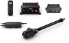
Item Description NMEA 2000 network ECU CCU ECU power cable CCU cable Throttle actuator Steering actuator Important Considerations You must connect the helm control or compatible Garmin chartplotter and the CCU to a NMEA 2000 network using the included T-connectors (NMEA 2000 Connection Considerations, page 3). If there is not an existing NMEA 2000 network on your boat, you can build one using the supplied cables and connectors (Building a Basic NMEA 2000 Network for the Autopilot System, page 6). You can mount the CCU in a non-submerged location near the center of the boat, in any orientation (CCU Mounting and Connection Considerations, page 2). Mount the CCU away from sources of magnetic interference. You must connect the ECU to a 12 to 24 Vdc power source. To extend this cable, use the correct wire gauge (Power Cable Extensions, page 4). To extend this cable to reach the ECU, you may need to use cable extensions (sold separately) (CCU Mounting and Connection Considerations, page 2). The throttle actuator controls the speed of the motor. The throttle actuator power cable cannot be cut or extended. This diagram shows only the electrical connection to the throttle actuator. Detailed installation instructions are included with the throttle actuator. The steering actuator steers the motor. The steering actuator power cable cannot be cut or extended. Mounting and Connection Considerations The autopilot components connect to each other and to power using the included cables. Ensure that the correct cables reach each component and that each component is in an acceptable location before mounting or wiring any components. CCU Mounting and Connection Considerations • The CCU is the primary sensor of the Reactor 40 Kicker autopilot system. For best performance, observe these considerations when selecting a mounting location. ◦ A handheld compass should be used to test for magnetic interference in the area where the CCU is to be mounted(Testing a Location for Magnetic Interference, page 2). ◦ The CCU should be mounted on a rigid surface for best performance. • Mounting screws are provided with the CCU. If you use mounting hardware other than the provided screws, the hardware must be quality stainless or brass material to avoid magnetic interference with the CCU. Test any mounting hardware with a handheld compass to make sure no magnetic fields are present in the hardware. • The CCU cable connects the CCU to the ECU and is 5 m (16 ft.) long. ◦ If the CCU cannot be mounted within 5 m (16 ft.) of the ECU, extension cables are available from your local Garmin dealer or at www.garmin.com. ◦ This cable must not be cut. Finding the Best Mounting Location 1 Create a list of all suitable mounting locations for the CCU. Suitable mounting locations should not be within 60 cm (2 ft.) of the following: 2 • Iron • Magnets • High-current wires • Intermittently-running pumps, such as head pumps and live well pumps A large magnet, such as a subwoofer-speaker magnet, should be no closer than 1.5 m (5 ft.) to any of the mounting locations. 2 Locate the center of rotation of the boat, and measure the distance between the center of rotation and each of the suitable mounting locations you listed in step 1. 3 Select the location closest to the center of rotation. If more than one location is approximately the same distance from the center of rotation, you should select the location that best meets these considerations. • The best location is closest to the centerline of the boat. • The best location is lower in the boat. • The best location is slightly forward in the boat. Testing a Location for Magnetic Interference You can use a handheld compass to test a mounting location for magnetic interference. 1 Hold a handheld compass in the CCU mounting location. 2 Move the compass six inches to the left of the location, then six inches to the right, observe the needle, and select an action: • If the compass needle moves more than three degrees during this step, magnetic interference is present. Select a new mounting location and repeat the test. • If the compass needle does not move, or moves less than three degrees, proceed to the next step. 3 Repeat this process while moving the compass above and below the mounting location. 4 Repeat this process while moving the compass in front of and behind the mounting location. ECU Mounting and Connection Considerations • The ECU can be mounted on a flat surface, facing any direction. • Mounting screws are included with the ECU, but you may need to provide different screws if the supplied screws are not suitable for the mounting surface. • The ECU must be mounted in a location where it will not be submerged or exposed to wash down. • The ECU power cable connects to the boat battery, and it can be extended if needed (Power Cable Extensions, page 4). Steering Actuator Installation and Connection Considerations • The steering actuator mounts in the tilt tube of your motor and uses a steering arm and linkage system to steer. • If you plan to use this autopilot system on a boat in salt water, you should review the saltwater considerations before installing the steering actuator (Saltwater Considerations, page 3). • You can install the steering actuator from either side of the tilt tube. • You must install the steering actuator before permanently mounting the ECU. • You cannot extend the cable that connects the steering actuator to the ECU.
-
 1
1 -
 2
2 -
 3
3 -
 4
4 -
 5
5 -
 6
6 -
 7
7 -
 8
8 -
9
-
10
 |
 |
