Garmin Reactor 40 Kicker Autopilot Throttle Actuator Installation Instructions - Page 1
Garmin Reactor 40 Kicker Autopilot Manual
 |
View all Garmin Reactor 40 Kicker Autopilot manuals
Add to My Manuals
Save this manual to your list of manuals |
Page 1 highlights
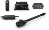
REACTOR™ 40 KICKER THROTTLE ACTUATOR INSTALLATION INSTRUCTIONS Important Safety Information WARNING See the Important Safety and Product Information guide in the product box for product warnings and other important information. You are responsible for the safe and prudent operation of your vessel. The autopilot is a tool that enhances your capability to operate your boat. It does not relieve you of the responsibility of safely operating your boat. Avoid navigational hazards and never leave the helm unattended. Always be prepared to promptly regain manual control of your boat. If your motor features a kill switch, you should know how to operate it in case of an emergency. If your motor does not feature a kill switch, you should install one before installing the autopilot system. Learn to operate the autopilot on calm and hazard-free open water. Use caution when operating the autopilot near hazards in the water, such as docks, pilings, and other boats. CAUTION When in use, beware of hot surfaces on the heat-sink, motor, and solenoid components. When in use, beware the risk of entrapment or pinching from moving parts. Failure to install and maintain this equipment in accordance with these instructions could result in damage or injury. Tools Needed • Wrenches • Phillips screwdriver • Marine sealant • Loctite® thread lock (for Honda® motor installs) Parts Identification The throttle actuator is the component of the Reactor 40 Kicker autopilot system that controls the speed of the motor. You must install the throttle actuator inside the motor housing and connect it to the carburetor throttle lever using the linkage parts supplied in this package. Different motor types require different linkage parts, and the parts are separated into separate bags. These instructions refer to the labels on the bags when discussing the parts needed for different motor types. Throttle Actuator Number Part Notes Throttle cable Connects to the carburetor linkage to pull open the carburetor and control the speed of the motor. Consult the section for your motor type for details about how to connect this cable to the carburetor linkage. RPM cable Connects to the spark plug to measure the motor RPM (Connecting the RPM Cable, page 5). ECU cable Connects the throttle actuator to the ECU of the autopilot system (Connecting the Throttle Actuator to the ECU, page 6). Parts Bags You should refer to this table to determine which parts apply to your motor type. Common parts. These parts are used when installing the actuator on all motor types. Parts for 8 through 9.9 horsepower Yamaha® motors. Parts for 15 through 20 horsepower Yamaha motors. Parts for 8 through 9.9 horsepower Mercury® motors. Parts for 15 through 20 horsepower Mercury EFI motors. Parts for 8 through 20 horsepower Honda motors. Installation Preparation Mounting and Connection Considerations When preparing to install the throttle actuator, observe the following considerations: • You must install the throttle actuator inside the motor housing. • Most motors use a throttle linkage to control the carburetor throttle lever. You should replace the factory-installed throttle linkage with the provided throttle linkage to prevent the throttle actuator from back-driving the throttle on the tiller (Tiller Back Drive Considerations, page 1). • You must secure the throttle cable to the motor manifold and connect it to the carburetor throttle lever on the motor using the included bracket and linkage specific to your motor type. • You can place the throttle actuator box in any available space inside the motor housing after you secure the throttle cable to the manifold and route the other cables. You can use the included large zip ties to secure the throttle actuator box inside the motor housing to keep it from moving during use. • You must secure the RPM cable to the outside of a spark plug cable (Connecting the RPM Cable, page 5). • You must connect the throttle actuator to the ECU of the autopilot system using the provided cable run from inside the motor housing (Connecting the Throttle Actuator to the ECU, page 6). Tiller Back Drive Considerations Most motors use a throttle linkage to control the carburetor throttle lever. This linkage opens and closes the carburetor when you adjust the throttle on the tiller arm. Because the autopilot throttle actuator controls the speed of the motor from inside the motor housing, you should replace the factoryinstalled throttle linkage with the provided throttle linkage. This prevents the throttle actuator from back-driving the throttle on the tiller arm, but still allows you to use the throttle on the tiller arm when you are not using the autopilot system to control the motor. See the connections diagram for your motor type to locate the existing throttle linkage and replace it with the included linkage. August 2019 190-02451-94_0B
-
 1
1 -
 2
2 -
 3
3 -
 4
4 -
 5
5 -
 6
6
 |
 |
