Gateway 9510 Gateway 9510 Setup Poster - Page 1
Gateway 9510 Manual
 |
View all Gateway 9510 manuals
Add to My Manuals
Save this manual to your list of manuals |
Page 1 highlights
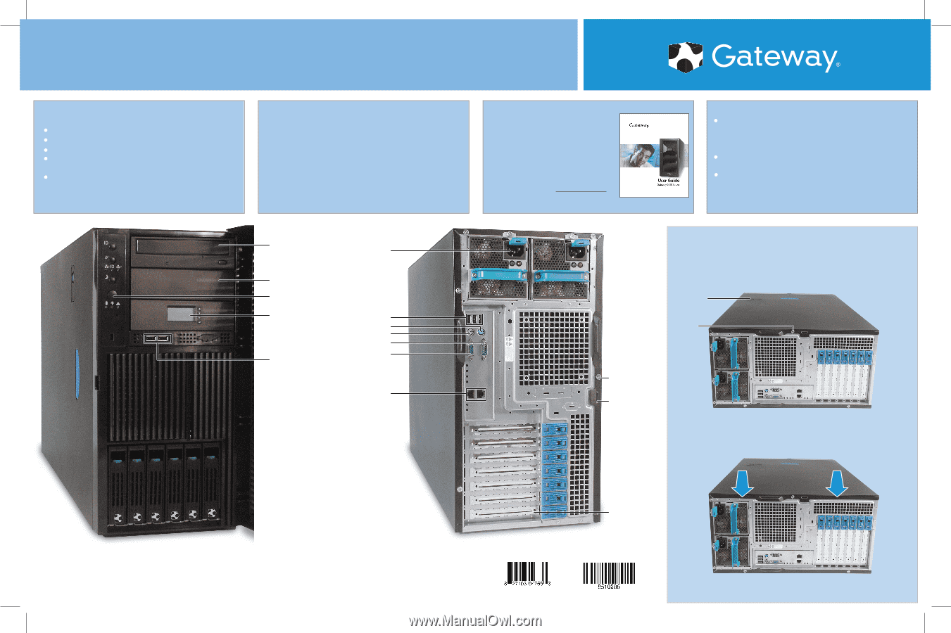
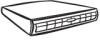
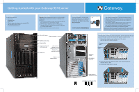
Getting started with your Gateway 9510 server Box Contents In this box you will find: Your server Accessory box Power cord CDs (for more information on the included CDs, see Using Your Server CDs) Purchased software boxes Unpacking the Box Warning: When unpacking your server, use two people or a lifting device to avoid personal injury or damage to the equipment. 1. Remove the accessory box(es) and make sure that all the components you ordered are present. 2. With the help of another person or a lifting device, carefully remove the server from the carton and place it on a flat, stable surface. 3. Remove the foam inserts from the server. CD or DVD drive Power connector Additional drive bay Power button Local control panel (LCP)(optional) USB ports USB ports Mouse port Keyboard port Serial port Monitor port Gigabit network ports Getting help For more information, see your user guide. To access your user guide on the System Companion CD, insert the CD into the CD drive, then click Documentation. For Customer Care, go to support.gateway.com, or call: 877-485-1464 (US) and choose option 6. Using your server CDs The System Companion CD contains hardware drivers, software utilities, and documentation for your server and its components. The CD can also automate the installation of your operating system. The Gateway Systems Manager CD contains software for monitoring Gateway servers and storage solutions. The operating system CD (if included) contains software for installing and reinstalling your operating system. Note: If you ordered your server with the operating system already installed by Gateway, in most cases it is completely installed and the basic settings are already configured. The Windows Small Business Server operating system may require additional installation, depending on the version you ordered. See your operating system's documentation for instructions on completing the installation or configuring advanced settings for your specific network. Opening your case For instructions on removing server components, see the label inside the side panel of the case or your user guide on the System Companion CD. 1. Remove the shipping screw on the back of the server. Lay the case on its side for stability. Release latch Shipping screw Shipping screw Kensington lock slot 2. Press the latch, then slide the access cover toward the back of the case about ½ inch. 3. Lift the panel away from the server. EMI shield for expansion cards A MAN 9510 SETUP PSTR R0 01/05
-
 1
1
 |
 |