Gateway GT5422E 8512041 - Gateway Hardware Reference Guide (5-bay uATX Case) - Page 52
sure that Pin 1 on the processor indicated by
 |
View all Gateway GT5422E manuals
Add to My Manuals
Save this manual to your list of manuals |
Page 52 highlights
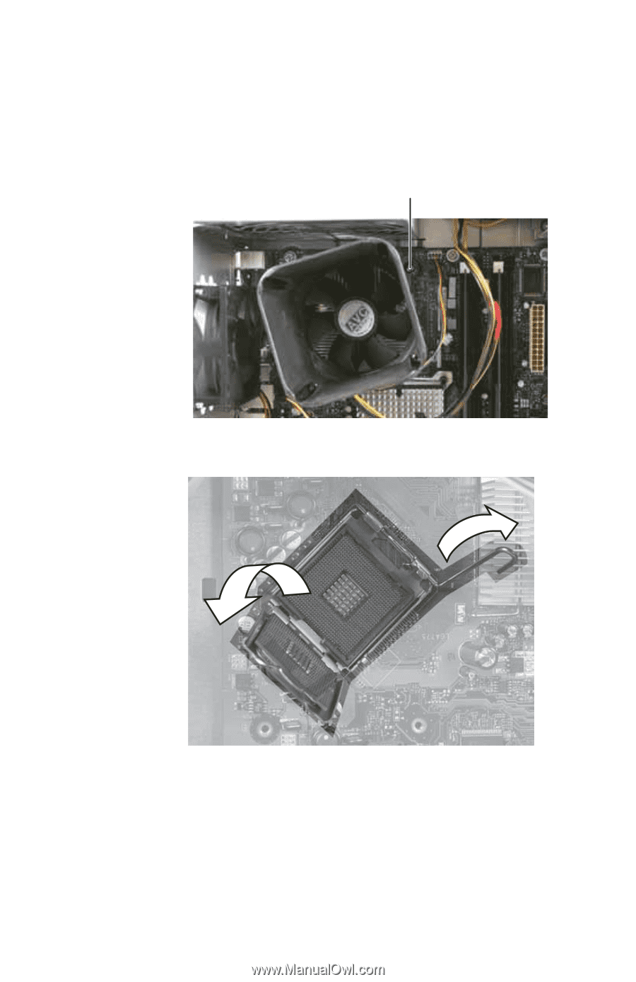
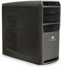
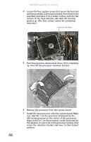
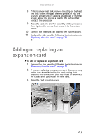
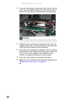
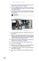
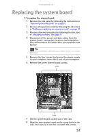
CHAPTER 4: Upgrading Your Computer 4 Loosen the four captive screws that secure the heat sink and fan assembly to the system board, then remove the assembly and place it on a stable surface with the flat surface of the heat sink (the side with the thermal grease) up. (The four screws cannot be completely removed.) Screws (only one shown) 5 Push the processor release lever down, lift it completely up, then lift the processor retention bracket. 6 Remove the processor from the system board. 7 Install the new processor onto the system board. Make sure that Pin 1 on the processor (indicated by the silk-screened arrow on the corner of the processor) aligns with Pin 1 on the processor socket (indicated by the absence of a pin hole in the processor socket), then return the retention bracket and lever to their locked position. 46
-
 1
1 -
2
-
3
-
4
-
5
-
6
-
7
-
8
-
9
-
10
-
11
-
12
-
13
-
14
-
15
-
16
-
17
-
18
-
19
-
20
-
21
-
22
-
23
-
24
-
25
-
26
-
27
-
28
-
29
-
30
-
31
-
32
-
33
-
34
-
35
-
36
-
37
-
38
-
39
-
40
-
41
-
42
-
43
-
44
-
45
-
46
-
 47
47 -
 48
48 -
 49
49 -
 50
50 -
 51
51 -
 52
52 -
 53
53 -
 54
54 -
 55
55 -
 56
56 -
 57
57 -
58
-
59
-
60
-
61
-
62
-
63
-
64
-
65
-
66
-
67
-
68
-
69
-
70
-
71
-
72
-
73
-
74
-
75
-
76
-
77
-
78
-
79
-
80
-
81
-
82
-
83
-
84
-
85
-
86
-
87
-
88
-
89
-
90
-
91
-
92
-
93
-
94
-
95
-
96
-
97
-
98
-
99
-
100
-
101
-
102
-
103
-
104
-
105
-
106
-
107
-
108
-
109
-
110
-
111
-
112
-
113
-
114
-
115
-
116
-
117
-
118
-
119
-
120
-
121
-
122
-
123
-
124
-
125
-
126
-
127
-
128
-
129
-
130
-
131
-
132
 |
 |