GE 60-770 Installation Instructions - Page 3
Mounting the Module in an Advent Cabinet, Mounting the Module in a Concord, Cabinet - my turn
 |
UPC - 046188092215
View all GE 60-770 manuals
Add to My Manuals
Save this manual to your list of manuals |
Page 3 highlights
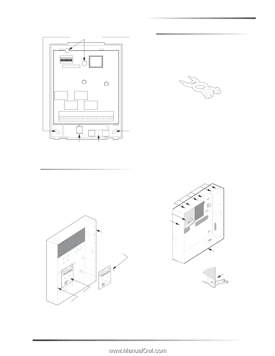
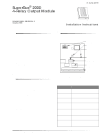
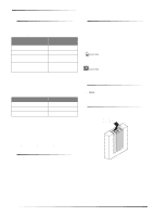
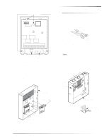
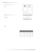
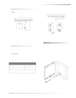
MOUNTING HOLES Installation Mounting the Module in a Concord Cabinet 1. Remove AC panel power and disconnect the backup battery. 2. Remove and discard the module cover (Figure 2). 3. Insert a support standoff as shown in Figure 5 (sup- plied with panel) into the panel circuit board. SUPPORT STANDOFF 1 2 3 4 5 6 7 8 9 10 11 12 13 14 15 16 17 18 MAGNET CLIP REED SWITCH HOLDER 9710G02B.DSF Figure 3. Mounting Holes Mounting the Module in an Advent Cabinet 1. Remove panel AC power and disconnect the backup battery(s). 2. Remove the module cover and set it aside (Figure 2). 3. Turn the module upside down and line up the holes on the back-plate at the desired location (Figure 4). 4. Secure the back-plate to the cabinet using three ¼-inch #6-32 self-tapping screws (not included). PANEL END MODULE END 8573g64A.DSF Figure 5. Support Standoff 4. Slide the module back-plate onto the two clips located on the top-left corner or center of the cabinet (Figure 6). Note The two mounting clips in the top-right corner of the cabinet are designated for a receiver module, but if a receiver module is not being used, the mounting clips may be used for the 4-Relay Output Module. 5. Push the lower-right corner of the module onto the support standoff (see detail in Figure 6). 6. Gently press the module up and onto the cabinet side tab. USABLE MOUNTING CLIPS (6) CARD ON MODULE BACK-PLATES SIDE TAB PANEL CABINET (COVER NOT SHOWN) MOUNT WITH SELF TAPPING SCREWS MOUNTED MODULE ROOM FOR 3RD 9712G11A.DSF MODULE Figure 4. Mounting Module in Advent Cabinet 9712G08A.DSF PANEL CABINET (COVER NOT SHOWN) DETAIL SUPPORT STANDOFF (Included with Concord panel accessory package) Figure 6. Mounting Module in Concord Cabinet SuperBus® 2000 4-Relay Output Module 3
-
 1
1 -
 2
2 -
 3
3 -
 4
4 -
 5
5 -
 6
6 -
 7
7 -
 8
8
 |
 |