GE 60-807-95R Installation Instructions - Page 4
Troubleshooting, Specifications, Notices - sensor
 |
UPC - 782136403831
View all GE 60-807-95R manuals
Add to My Manuals
Save this manual to your list of manuals |
Page 4 highlights
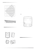
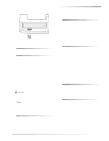
Troubleshooting before activating the walk test mode. See Figure 7 for battery locations. Specifications PIR COVER PWB COVER TABS LENS SENSOR BODY MOUNTING PLATE TAMPER SWITCH 8362G02A.DS4 Figure 7. PIR Components, Battery Locations, & Tamper Switch Troubleshooting Use the following guidelines if the system does not respond correctly when the sensor is activated. Check programming and re-program sensor into panel if necessary. Move the sensor to another location and test for correct response. To relocate a sensor: 1. Test the sensor a few inches from the original position. 2. Increase the distance from the original position and retest until an acceptable location is found. 3. Mount the sensor in the new location. 4. If no location is acceptable, test the sensor as described below: Test a known good sensor at the same location. If the system does not respond, avoid mounting a sensor at that location. If the replacement sensor functions, return the problem sensor for repair or replacement. Power source: 2 AA alkaline batteries Typical battery life: 2-4 years at 68° F Temperature range: 32° to 120° F (Non-pet applications) 60° to 120° F (Pet applications) Dimensions: L = 2.875" X W = 2.375" X H = 1.875" Notices These devices comply with part 15 of the FCC rules. Operation is subject to the following two conditions: These devices may not cause harmful interference. These devices must accept any interference received, including interference that may cause undesired operation. Changes or modifications not expressly approved by Interactive Technologies, Inc. can void the users' authority to operate the equipment. ITI is a registered trademark of Interactive Technologies, Inc. 4 ITI® Pet Immune SAW PIR Motion Sensor
-
 1
1 -
 2
2 -
 3
3 -
 4
4
 |
 |