GE 60-886-95 Installation Instructions - Page 2
Installation - shock sensor
 |
UPC - 782136700015
View all GE 60-886-95 manuals
Add to My Manuals
Save this manual to your list of manuals |
Page 2 highlights
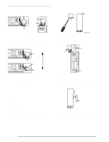
Installation Shock Element ON 1 2 3 4 5 6 LOGO Shock Element Screw Terminals LOGO Screw Terminals ON 1 2 3 4 5 6 Figure 3. Positioning shock element according to mounting orientation on a vertical surface On a horizontal surface (sill or ledge), any orientation is allowed, but certain sensor element orientations are better than others. The element is much better at detecting horizontal vibrations perpendicular to its writing than parallel (see Figure 4). Perpendicular (Good) ON 1 2 3 4 5 6 LOGO Shock Element Screw Terminals Shock Element Direction of Vibration Top End Slot 8 3 9 4 g 0 2 b .d s f Figure 5. Remove the sensor cover 2. Using the flathead mounting screws, secure the base to the mounting surface either vertically or horizontally as required (see Figure 6). LOGO Shock Element ON 1 2 3 4 5 6 Mounting Hole (Located Under Shock Element) LOGO ON 1 2 3 4 5 6 Screw Terminals Parallel (Bad) Figure 4. Positioning shock elements for horizontal surface mounting Tools and Supplies ❑ Control panel installation instructions ❑ Phillips screwdriver ❑ Slotted screwdriver (to pry off the cover) ❑ Two #6 x 3/4" flathead screws for mounting the sensor (included) ❑ Two #6 x 5/8" screws for mounting the magnet (included) Installation Caution! You must be free of all static electricity when handling electronic components. Touch a grounded, bare metal surface before touching a circuit board or wear a grounded wrist strap. 1. Insert a slotted screwdriver into the slot at the top end of the unit and remove the cover (see Figure 5). Mounting Hole Figure 6. Sensor base mounting holes 3. Position the shock element and press it firmly into its socket (see Figure 7). 4. If using the reed switch, use the two remaining screws to mount the magnet so that its arrow is aligned with the arrow on the sensor case (see Figure 7). Arrows Magnet Figure 7. Magnet alignment Important! You must disable the reed switch if you are not using it. If the reed switch is enabled but no magnet is installed, the sensor will be in a continuous alarm state. 2
-
 1
1 -
 2
2 -
 3
3 -
 4
4
 |
 |
