GE AJCQ12ACD Use and Care Manual - Page 8
About the controls on the air conditioner, Fan Cycle/Continuous - Cool
 |
View all GE AJCQ12ACD manuals
Add to My Manuals
Save this manual to your list of manuals |
Page 8 highlights
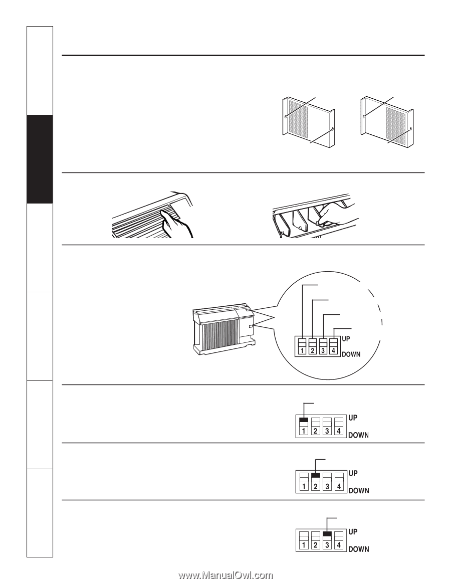
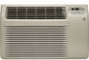
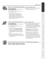
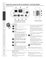
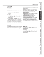
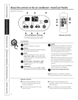
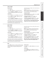
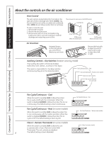
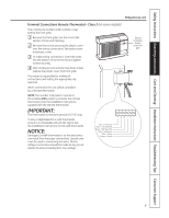
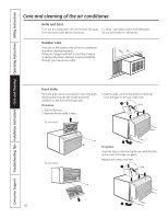
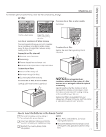
Consumer Support Troubleshooting Tips Installation Instructions Care and Cleaning Operating Instructions Safety Instructions About the controls on the air conditioner Vent Control The vent control is located behind the front grille on the right side of the air discharge area. When CLOSED, only the air inside the room will be circulated and conditioned. When OPEN, the vent allows outdoor fresh air exchange. To open or close the vent: 1. Remove the front grille. 2. Remove the vent card screw. 3. Remove vent card, turn it over and replace it by locating rear hole in card over locating pin inside air discharge and reattaching screw at front. The unit leaves the factory set at the CLOSE position. Locating hole Locating hole Screw hole OPEN position (Mesh end toward back) Screw hole CLOSE position (Mesh end toward front) Air Direction Horizontal louvers on the front grille let you control the air direction up and down. Remove the front grille to adjust the vertical louvers side-to-side to direct the air left or right. Auxiliary Controls - Dip Switches (location varies by model) The auxiliary dip switch controls are located behind the room cabinet-as shown in this figure. The owner is responsible for checking switches and ensuring they are in the desired position. Fan Cycle/Continuous - Cool Fan Cycle/Continuous - Heat (on some models) Class 2 (on some models) No function (reserved for future use) Fan Cycle/Continuous - Cool When this switch is enabled (UP), it allows the indoor fan to cycle on/off with the compressor. When this switch is disabled (DOWN), it allows the indoor fan to run continuously. The default setting is down (continuous). Fan Cycle/Continuous - Cool Fan Cycle/Continuous - Heat (on some models) When this switch is enabled (UP), it allows the indoor fan to run continuously with the heater operation. When this switch is disabled (DOWN), it allows the indoor fan to cycle on/off. The default setting is down (cyclic). Fan Cycle/Continuous - Heat (on some models) Class 2 - Remote Thermostat (on some models) When this switch is enabled (UP), it allows the unit to operate with a Class 2 Remote Control Wall Thermostat. The unit controls are disabled. 8 The default setting is down (disabled). Class 2 (on some models)
-
 1
1 -
2
-
 3
3 -
 4
4 -
 5
5 -
 6
6 -
 7
7 -
 8
8 -
 9
9 -
 10
10 -
 11
11 -
 12
12 -
 13
13 -
14
-
15
-
16
-
17
-
18
-
19
-
20
-
21
-
22
-
23
-
24
-
25
-
26
-
27
-
28
-
29
-
30
-
31
-
32
-
33
-
34
-
35
-
36
-
37
-
38
-
39
-
40
-
41
-
42
-
43
-
44
-
45
-
46
-
47
-
48
-
49
-
50
-
51
-
52
-
53
-
54
-
55
-
56
-
57
-
58
-
59
-
60
-
61
-
62
-
63
-
64
-
65
-
66
-
67
-
68
-
69
-
70
-
71
-
72
 |
 |