GE C2S980SEMSS Quick Specs - Page 1
GE C2S980SEMSS - 30" Dual Fuel Range Manual
 |
UPC - 084691165118
View all GE C2S980SEMSS manuals
Add to My Manuals
Save this manual to your list of manuals |
Page 1 highlights
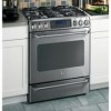
C2S980SEMSS GE Café™ 30" Free-Standing Dual-Fuel Range with Baking Drawer Dimensions and Installation Information (in inches) Electrical Requirements: 240v/208v; 60Hz, 40A Effective January 1, 1996, the National Electrical Code requires that new construction (not existing) utilize a 4-conductor connection to an electric range. Receptacle Locations: Locally approved flexible service cord or conduit must be used because terminals are not accessible after range installation. See shaded area in drawing for location of electrical outlet box. Recommended outlet locations allow range to be installed directly against wall. Note: 30" ranges conform to U.L. requirements for 0" spacing from adjacent walls below countertops. To reduce possibility of scorching walls, engineering recommends a minimum of 1-1/2" spacing to allow for possible extended, high-heat, no-load heating element operation. Installation information: Before installing, consult installation instructions packed with product for current dimensional data. Optional accessories: Tall backguard JXS8055 (Available at additional cost) 30" 30" 26-1/2" 46-3/246"-1/2" 46-3/4" For answers to your Monogram,® GE Profile™ or GE® appliance questions, visit our website at geappliances.com or call GE Answer Center® service, 800.626.2000. 36-1/4"+_13/46*-1/4"+_1/4* *Dimension from floor to top of the cooktop. Floo*Dr tiomtoepnosfiorenafrrom floor to top of vent trim is 37-1/4th" e cooktop. Floor to top of rear vent trim is 37-1/4" NOTE: Make gas connections on the left side and electrical conections on the cutout oripgehnt isnigdNtoc.ehunOeototfTlhuetEhetfet:orsMipgideahenkt eisaningdgd.ea33seo04lcfeotchn8ternice3aclticoonnRetlseheleeneocccgneotttrihlm3oieccin0mastslrepiocnauadrtlaleerldeltecalaertcoepcatetah.pceOtleaRerfbilseolleeoenocctrt.ohtremicmaleonudtleedt Recommended area for through-the-wall connection of pipe 39 Wall- Mounte3d 4 38 the electrical re length is paralle stub/shut-off valve. This area allowRsecommended area 39 Wall- Mounte flush installatiofnor through-the-wall to rear wall. connection of pipe 2-1/4 stub/shut-off valve. 7-1/2 2 This area allows Recommendedfluasreha ifnosr tallation through-the-flotoor creonanrewctaiolnl. Product is shipped with 4-prong plug. Recommen2d-e1d/4outlet is of pipe stub/shut-off valve. a NEMA 14-50R receptacle. 7-1/2 2 All GE ranges are equipped with Recommended area for an Anti-Tip device. The installation of this device is an important, through-the-roeffqtluhoiererdaonsgtreep. icn toheninsntalleatiocn tion of pipe stub/shut-off valve. Product is shippe plug. Recommen a NEMA 14-50R Specification Revised 2/11 221218
-
 1
1 -
 2
2
 |
 |
