GE DPVH880EJWW Owners Manual - Page 14
Installation Instructions, LOCATION OF YOUR DRYER
 |
UPC - 084691169840
View all GE DPVH880EJWW manuals
Add to My Manuals
Save this manual to your list of manuals |
Page 14 highlights
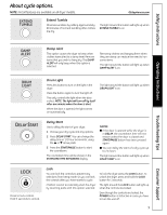
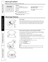
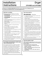
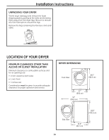
Installation Instructions UNPACKING YOUR DRYER Tilt the dryer sideways and remove the foam shipping pads by pulling at the sides and breaking them away from the dryer legs. Be sure to remove all of the foam pieces around the legs. Remove the bag containing the literature and serial cable. LOCATION OF YOUR DRYER MINIMUM CLEARANCE OTHER THAN ALCOVE OR CLOSET INSTALLATION Minimum clearance to combustible surfaces and for air openings are: • 0 inch clearance both sides • 1 inch front • 3 inches rear Consideration must be given to provide adequate clearance for proper operation and service. DRYER DIMENSIONS Front View 3399.15″ (910903.3cmcm)) 277″″ ((668.6 ccmm)) 5531″″ (13249.6.5ccmm) ) Side View 3399.1.5″″ (919003.3cmcm) ) 3233.3.54″″ (8(8457.1ccmm) 14
-
 1
1 -
2
-
3
-
4
-
5
-
6
-
7
-
8
-
 9
9 -
 10
10 -
 11
11 -
 12
12 -
 13
13 -
 14
14 -
 15
15 -
 16
16 -
 17
17 -
 18
18 -
 19
19 -
20
-
21
-
22
-
23
-
24
-
25
-
26
-
27
-
28
-
29
-
30
-
31
-
32
-
33
-
34
-
35
-
36
-
37
-
38
-
39
-
40
-
41
-
42
-
43
-
44
-
45
-
46
-
47
-
48
-
49
-
50
-
51
-
52
-
53
-
54
-
55
-
56
-
57
-
58
-
59
-
60
-
61
-
62
-
63
-
64
-
65
-
66
-
67
-
68
-
69
-
70
-
71
-
72
-
73
-
74
-
75
-
76
-
77
-
78
-
79
-
80
-
81
-
82
-
83
-
84
-
85
-
86
-
87
-
88
-
89
-
90
-
91
-
92
-
93
-
94
-
95
-
96
-
97
-
98
-
99
-
100
-
101
-
102
-
103
-
104
-
105
-
106
-
107
-
108
-
109
-
110
-
111
-
112
-
113
-
114
-
115
-
116
-
117
-
118
-
119
-
120
-
121
-
122
-
123
-
124
-
125
-
126
-
127
-
128
-
129
-
130
-
131
-
132
-
133
-
134
-
135
-
136
-
137
-
138
-
139
-
140
-
141
-
142
-
143
-
144
-
145
-
146
-
147
-
148
-
149
-
150
-
151
-
152
 |
 |
