GE DWXR463EG Installation Instructions - Page 2
Installation Instructions
 |
View all GE DWXR463EG manuals
Add to My Manuals
Save this manual to your list of manuals |
Page 2 highlights
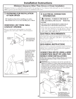
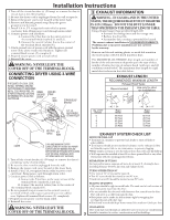
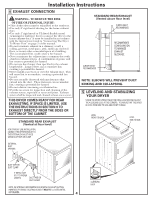
Installation Instructions Minimum Clearance Other Than Alcove or Closet Installation Minimum clearance to combustible surfaces and for air opening are: 0 in. clearance both sides and 1 in. rear. Consideration must be given to provide adequate clearance for installation and service. 1 PREPARING FOR INSTALLATION OF NEW DRYER TIP: Install your dryer before installing your washer. This will allow better access when installing dryer exhaust. REMOVING LINT FROM WALL EXHAUST OPENING • Remove and discard existing plastic or metal foil transition duct and replace with UL listed transition duct. WALL INTERNAL DUCT OPENING CHECK THAT EXHAUST HOOD DAMPER OPENS AND CLOSES FREELY. TILT THE DRYER SIDEWAYS AND REMOVE THE FOAM SHIPPING PADS BY PULLING AT THE SIDES AND BREAKING THEM AWAY FROM THE DRYER LEGS. BE SURE TO REMOVE ALL OF THE FOAM PIECES AROUND THE LEGS. 2 ELECTRICAL CONNECTION INFORMATION WARNING - TO REDUCE THE RISK OF FIRE, ELECTRICAL SHOCK AND PERSONAL INJURY: • DO NOT USE AN EXTENSION CORD OR AN ADAPTER PLUG WITH THIS APPLIANCE. Dryer must be electrically grounded in accordance with local codes and ordinances, or in the absence of local codes, in accordance with the NATIONAL ELECTRICAL CODE, ANSI/NFPA NO. 70. ELECTRICAL REQUIREMENTS This dryer must be connected to an individual branch circuit, protected by the required time-delay fuses or circuit breakers. A four or three-wire, single phase, 120/240V or 120/208V, 60Hz, 30 amp circuit is required. If the electric supply does not meet the above specifications, then call a licensed electrician. GROUNDING INSTRUCTIONS This dryer must be connected to a grounded metal, permanent wiring system, or an equipment-grounding conductor must be run with the circuit conductors and connected to the equipmentgrounding terminal on the appliance. CONNECTING DRYER USING 4-WIRE CONNECTION (MUST BE USED FOR MOBILE HOME INSTALLATION) NOTES: SInce January 1,1996, the National Electric code requires that the new constructions utilize a 4-wire connection to an electric dryer WARNING:Only a 4-conductor cord shall be used when the appliance is installed in a location where grounding through the neutral conductor is prohibited. Grounding through the neutral is prohibited for the new branch-circuit installations, mobile homes, recreational vehicles, and areas where local codes prohibit grounding through the neutral conduction. REMOVE GROUND STRAP AND DISCARD. KEEP GREEN GROUND SCREW SCREWS (3) HOT WIRE L1 N L2 RELOCATE GREEN GROUND SCREW HERE GREEN OR YELLOW WIRE STRAIN RELIEF BRACKET COVER 2 NEUTRAL (White) HOT WIRE 3/4", UL RECOGNIZED STRAIN RELIEF 4 #10 AWG MINIMUM COPPER CONDUCTORS OR 120/240V 30A POWER SUPPLY CORD KIT MARKED FOR USE WITH DRYERS & PROVIDED WITH CLOSED LOOP OR SPADE TERMINALS WITH UPTURNED ENDS (NOT SUPPLIED).
-
 1
1 -
 2
2 -
 3
3 -
 4
4 -
 5
5 -
 6
6 -
 7
7 -
 8
8
 |
 |
