GE GCG17 Installation Instructions - Page 3
Design Information - gcg1700 compactor
 |
View all GE GCG17 manuals
Add to My Manuals
Save this manual to your list of manuals |
Page 3 highlights
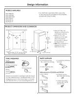
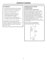
Design Information MODELS AVAILABLE GCG1580 SS GCG1500 BB GCG1500 WW GCG1700 II* ZCGS150 SS ZCGP150 II* *For ZCGP150 II and GCG1700 II, also refer to the instructions provided on the template packed with those models. PRODUCT DIMENSIONS AND CLEARANCES 24" (61 cm) min. 15" (38.1 cm) min. 34" (86.4 cm) to 35" (88.9 cm) 33-3/4" (85.7 cm) min. to 35" (88.9 cm) max. • Allow 23″ (58.4 cm) clearance at the front for a full drawer opening. • Allow 6″ (15.2 cm) clearance on the right side to the nearest vertical wall or cabinet for bag removal. • Note: This compactor is designed for built-in applications only. Locate the outlet 18" (45.7 cm) min. from the floor, 3" (7.6 cm) min. from either side 23" (58.4 cm) 14-7/8" (37.8 cm) TOOLS REQUIRED • Level • Gloves •Phillips screwdriver • Pliers •Measuring tape All parts are located in a package inside the drawer. To order additional parts, call 800.626.2002 or visit GEAppliances.com in the United States. In Canada, call 1.800.561.3344 or visit www.GEAppliances.ca. PARTS SUPPLIED • 6 mounting screws, #8 x 11/16" (1.8 cm) long • 2 countertop retaining brackets • 2 side-mounting clips Additional parts for ZCGS150SS and ZCGP150II • Door toekick • 8 Toekick screws, #8 x 5/16" (0.8 cm) long • Top toekick • Base toekick • 4 White mounting screws, #8 x 11/16" (1.8 cm) long 3
-
 1
1 -
 2
2 -
 3
3 -
 4
4 -
 5
5 -
 6
6 -
 7
7 -
 8
8 -
 9
9 -
10
-
11
-
12
-
13
-
14
-
15
-
16
-
17
-
18
-
19
-
20
-
21
-
22
-
23
-
24
 |
 |
