GE GFDS170GHWW Installation Instructions - Page 16
EXHAUSTING THE DRYER cont., Installation Instructions, FINAL SETUP
 |
View all GE GFDS170GHWW manuals
Add to My Manuals
Save this manual to your list of manuals |
Page 16 highlights
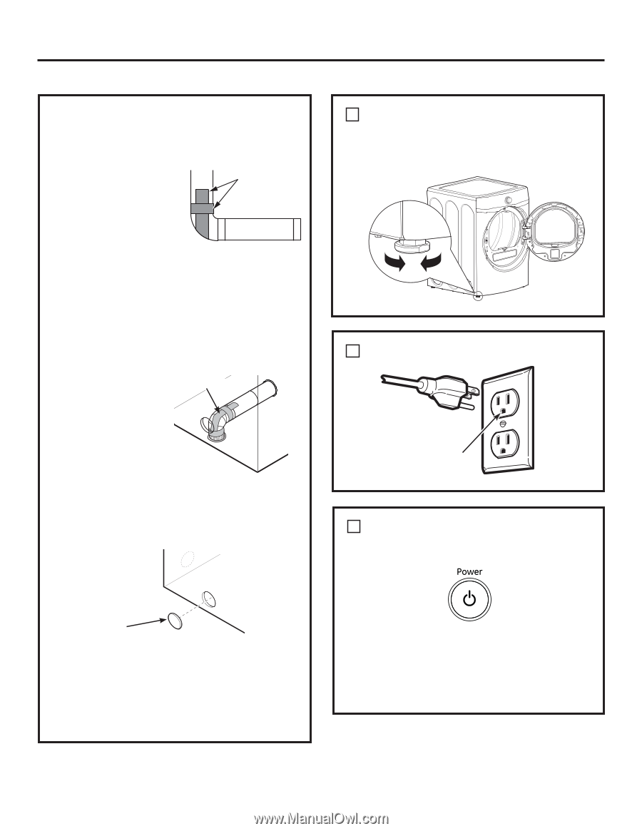
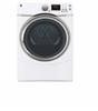
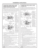
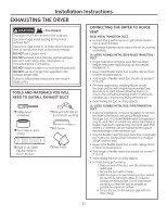
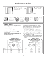
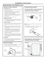
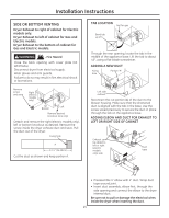
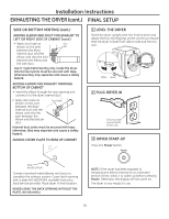
Installation Instructions EXHAUSTING THE DRYER (cont.) FINAL SETUP SIDE OR BOTTOM VENTING (cont.) ADDING ELBOW AND DUCT FOR EXHAUST TO LEFT OR RIGHT SIDE OF CABINET (cont.) • Apply duct tape as DUCT shown on the joint TAPE between the dryer internal duct and the elbow, and also the joint between the elbow and the side duct. Use 4" rigid metal ducting only inside the dryer. Internal duct joints must be secured with tape, otherwise they may separate and cause a safety hazard. ADDING ELBOW FOR EXHAUST THROUGH BOTTOM OF CABINET • Insert the elbow through the rear opening and connect it to the dryer internal duct. • Apply duct tape as shown on the joint between the dryer internal duct and the elbow, and also the joint between the elbow and the bottom duct. Duct tape Internal duct joints must be secured with tape; otherwise, they may separate and cause a safety hazard. ADDING COVER PLATE TO REAR OF CABINET 1 LEVEL THE DRYER Stand the dryer upright near the final location and adjust the four leveling legs at the corners to ensure that the dryer is level from side to side and front to rear. Raise Lower 2 PLUG DRYER IN Ensure proper ground exists before use. 3 DRYER START-UP Press the Power button. Plate (Kit WE1M454) Connect standard metal elbows and ducts to complete the exhaust system. Cover back opening with a plate (Kit WE1M454) available from your local service provider. Place dryer in final location. NEVER LEAVE THE BACK OPENING WITHOUT THE PLATE. (Kit WE1M454.) NOTE: If the dryer has been exposed to temperatures below freezing for an extended period of time, allow it to warm up before pressing Power. Otherwise, the display will not come on. The dryer is now ready for use. 16
-
 1
1 -
2
-
3
-
4
-
5
-
6
-
7
-
8
-
9
-
10
-
 11
11 -
 12
12 -
 13
13 -
 14
14 -
 15
15 -
 16
16 -
 17
17 -
 18
18 -
 19
19 -
 20
20 -
 21
21 -
22
-
23
-
24
-
25
-
26
-
27
-
28
-
29
-
30
-
31
-
32
 |
 |