GE JGP933 Installation Instructions - Page 6
iNstallatION iNstRUctIONs, inSTALLATion-gAS ConneCTionS
 |
View all GE JGP933 manuals
Add to My Manuals
Save this manual to your list of manuals |
Page 6 highlights
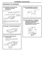
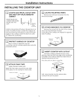
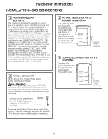
Installation Instructions Installation-GAS Connections 1 Provide Adequate Gas Supply This cooktop is designed to operate on natural gas at 4″ of water column manifold pressure and 7″ of water column (W.C.) supply pressure. It is shipped from the factory set for natural gas. The convertible pressure regulator supplied with the unit must be connected in series with the manifold of the cooktop and must remain in series with the supply line regardless of whether natural or L.P. gas is being used. FOR PROPER OPERATION, THE MAXIMUM INLET PRESSURE TO THE REGULATOR MUST BE NO MORE THAN 14″ OF WATER COLUMN PRESSURE. For checking the regulator, the inlet pressure must be at least 1″ W.C.. (or 3.4 KPA) greater than the regulator output setting. If the regulator is set for 4″ W.C. of water column pressure, the inlet pressure must be at least 5″ W.C. If the regulator is set for 10″ W.C., the inlet pressure must be at least 11″ W.C.. The gas supply line to the cooktop should be 1/2″ or 3/4″ pipe. 2 Install Regulator NEVER REUSE OLD CONNECTORS WHEN INSTALLING THIS COOKTOP. WARNING: Never reuse old flexible connectors. The use of old flexible connectors can cause gas leaks and personal injury. Always use new flexible connectors when installing a gas appliance. Screw a section of pipe onto the inlet end of the pressure regulator and install the coupling. Pressure Regulator Coupling To reduce the likelihood of gas leaks, apply teflon tape or a thread compound approved for use with LP or Natural gases to all threaded connections. 3 Install Regulator onto burner box bottom Screw the regulator onto the burner box bottom pipe connection. Make sure the top of the regulator is facing towards the cabinet front, easily accessible through the cabinet doors. Pressure Regulator Coupling Shut-Off Valve Electrical Outlet 12″ Below Countertop 4 Complete connection with a coupling Complete the connection between the regulator pipe coupling and the shut-off valve. Pressure Regulator Coupling Shut-Off Valve Electrical Outlet 12″ Below Countertop 6
-
 1
1 -
 2
2 -
 3
3 -
 4
4 -
 5
5 -
 6
6 -
 7
7 -
 8
8 -
 9
9 -
 10
10 -
 11
11 -
 12
12 -
13
-
14
-
15
-
16
-
17
-
18
-
19
-
20
-
21
-
22
-
23
-
24
-
25
-
26
-
27
-
28
-
29
-
30
-
31
-
32
 |
 |
