GE JP328SKSS Use and Care Manual - Page 11
Preparation, Install The Junction Box, Install The Cooktop, Secure The Cooktop, Make Electrical - ratings
 |
UPC - 084691130871
View all GE JP328SKSS manuals
Add to My Manuals
Save this manual to your list of manuals |
Page 11 highlights
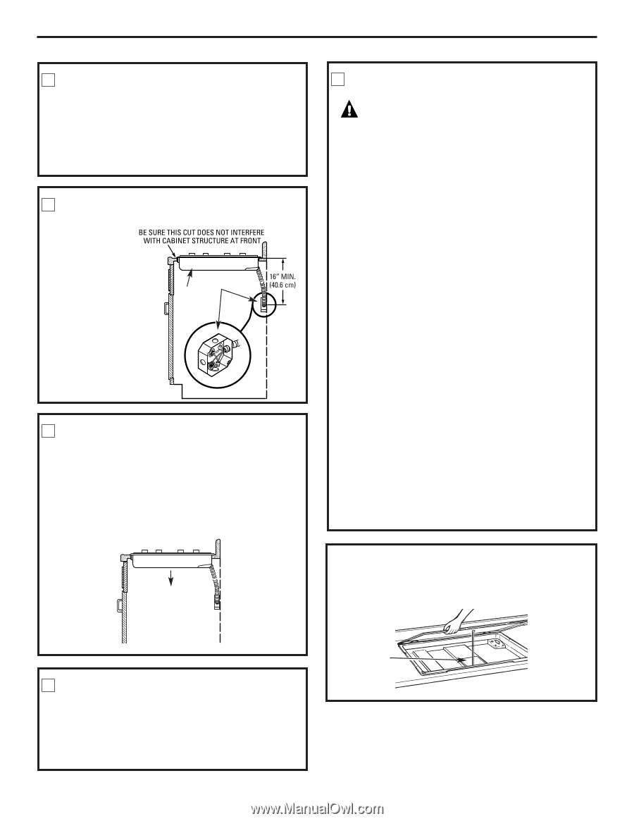
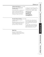
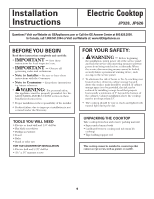
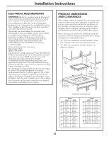
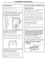
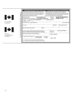
Installation Instructions 1 PREPARATION Before installing the cooktop or moving it to another location, have the electrician verify: • That your home is provided with adequate electrical service. • That the addition of the cooktop will not overload the household circuit on which it is used. 2 INSTALL THE JUNCTION BOX Install an approved junction box where it will be easily accessible through the front of the cabinet where cooktop will be located. See the illustration at right for the suggested mounting location. Junction Tub box 3 INSTALL THE COOKTOP Install the cooktop in the cutout opening. NOTE: If the cooktop is being installed in a blind counter (one with no cabinet opening below), wire connections must be made before putting the cooktop into the cutout. Maintain 5″ (12.7 cm) minimum vertical clearance between the cooktop bottom and any combustible surfaces. 5″ (12.7 cm) Min. Vertical Clearance 5 MAKE ELECTRICAL CONNECTIONS WARNING The electrical power to the cooktop supply line must be shut off while line connections are being made. Failure to do so could result in serious injury or death. When making the wire connections, use the entire length of conduit provided (3 feet). The conduit must not be cut. Connect the red and black leads from the cooktop conduit to the corresponding leads in the junction box. The power leads supplied with this appliance are UL recognized for connection to larger gauge household wiring. The insulation of the leads is rated at much higher temperatures than the temperature rating of household wiring. The current carrying capacity of the conductor is governed by the wire gauge and also the temperature rating of the insulation around the wire. GROUNDING INSTRUCTIONS The bare ground wire in the conduit is connected to the cooktop frame. When connecting to a 3 conductor branch circuit, if local codes permit, connect the bare ground connector lead of the cooktop to the branch circuit neutral (gray or white in color). Effective January 1, 1996, the National Electrical Code requires that new construction use a (4) conductor connection and will not permit grounding through neutral. If used in new construction after January 1, 1996, in a mobile home or recreational vehicle, or if local codes do not permit grounding through the neutral white lead, do the following: Attach the appliance grounding lead (green or bare copper) to the residence grounding conductor (green or bare copper) in accordance with local codes. MODEL AND SERIAL NUMBER LOCATION You can find them on a nameplate label under the cooktop. 4 SECURE THE COOKTOP Secure the tub of the cooktop to a standard counter with the wood screws shipped with the cooktop. Secure the tub of the cooktop to a tile counter with 4 masonry screws. These can be purchased at any hardware store. Location of nameplate label 11
-
 1
1 -
2
-
3
-
4
-
5
-
 6
6 -
 7
7 -
 8
8 -
 9
9 -
 10
10 -
 11
11 -
 12
12 -
 13
13 -
 14
14 -
 15
15 -
 16
16 -
17
-
18
-
19
-
20
-
21
-
22
-
23
-
24
-
25
-
26
-
27
-
28
-
29
-
30
-
31
-
32
-
33
-
34
-
35
-
36
-
37
-
38
-
39
-
40
-
41
-
42
-
43
-
44
-
45
-
46
-
47
-
48
 |
 |