GE JVM2052SNSS Installation Instructions - Page 6
Damage – Shipment/Installation, Parts Included, ADDITIONAL PARTS, HARDWARE PACKET
 |
UPC - 084691188094
View all GE JVM2052SNSS manuals
Add to My Manuals
Save this manual to your list of manuals |
Page 6 highlights
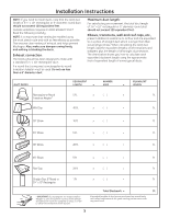
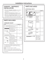
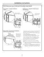
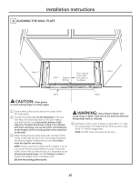
Installation Instructions DAMAGE - SHIPMENT/ INSTALLATION • If the unit is damaged in shipment, return the unit to the store in which it was bought for repair or replacement . • If the unit is damaged by the customer, repair or replacement is the responsibility of the customer. • If the unit is damaged by the installer (if other than the customer), repair or replacement must be made by arrangement between customer and installer. PARTS INCLUDED HARDWARE PACKET PART Lag Screws (1⁄4" x 2") (for wall stud holes) Toggle Bolts (1⁄4" x 3") (for drywall holes) Spring Toggle Heads (for toggle bolts) QUANTITY 4 4 4 Bolts 2 (for securing to the upper cabinet) Tapping Screws (1⁄8"x 1⁄2") (for attaching the damper duct connector) 1 black 2 bronze Power Cord Clamp and 1 Dark-Colored Mounting Screw (to hold the power cord) You will find the installation hardware contained in a packet with the unit. Check to make sure you have all these parts. NOTE: Some extra parts are included. NOTE: You need to install at least two lag screws into a 2" x 4" stud and four anchor bolts into the wall. Also, the mounting area must meet the 150 lbs. weight requirement . PARTS INCLUDED ADDITIONAL PARTS PART QUANTITY Upper Cabinet 1 Template Rear Wall 1 Template (3 pieces mounting plate only) Installation 1 Instructions Exhaust 1 Adapter Damper 1 Power Cord 1 Clamp Bushing (for the cord hole in a metal upper cabinet) 6
-
 1
1 -
 2
2 -
 3
3 -
 4
4 -
 5
5 -
 6
6 -
 7
7 -
 8
8 -
 9
9 -
 10
10 -
 11
11 -
 12
12 -
13
-
14
-
15
-
16
-
17
-
18
-
19
-
20
-
21
-
22
-
23
-
24
 |
 |
