GE PDW1860NSS Quick Specs - Page 2

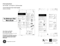
For Reference Only, Not to Scale

Page 2 highlights

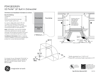
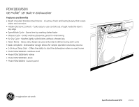
PDW1800/60N GE Profile™ 18" Built-In Dishwasher Custom Dishwasher Door Panel Template GE Pub. No. 031-30244 Top of Panel 2-5/32" (5.5 cm) 7-11/16" (19.5 cm) For Reference Only Not to Scale Drill 3/32" Pilot Hole 3/32" Deep 3/4" Thick Custom Panel Template Instructions for 18" Top Control Integrated Profile and Monogram Dishwasher Models The custom panel should be sized to your installation situation. See Step 1. For easier installation, the custom panel and custom handle should be attached before installing the dishwasher. Use this template to locate mounting screws and spacers on the custom panel. IMPORTANT • A custom handle must be installed onto the custom panel. Install the custom handle 4-1/2" max. from the top of the panel. PARTS INCLUDED: (2) Brackets (4) 1/2" Phillips at-head screws (2) Spacer pads (2) Metal spacers (2) 1" Phillips at-head screws (2) 3/4" Phillips round-head screws STEP 1 CUSTOM PANEL SIZE REQUIREMENTS HEIGHT Panel height should be 26-25/32" (68 cm). • The topof the custompanel mustbe withthe topof the door.The 1/2"minimumgap betweenthe topof the doorand the bottomof the countertopmustbe maintained. WIDTH Panel width must be 17-1/2" (44.4 cm). • If the panelwidthis less than17-1/2",it will notcover the dishwasher frame. IMPORTANT: To ensure optimum door balance performance, the custom panel must not weigh more than 8 lbs. Countertop Minimum 1/2" gap for clearance 1/2" minimum STEP 2 DRAW CENTERLINE • Ptlhaececustompanel on a surface withthe appearance side down. • Lothcaetveertical center of the panelat the top. • aUcsaerpenter's square to draw a centerlinefrom topto bottom. STEP 3 ALIGN TEMPLATE TO PANEL • teTrmimplateon the dottedline alongall sides. • Ptlhaecetemplateon the panel alignedwiththe top edgeand the centerline. Use tape to holdin place. IMPORTANT: If the template is not aligned with the top edge of the panel, the 1/2" minimum gap will not be maintained. This 1/2" minimum gap must be maintained to prevent condensation and damage to the control panel from screw heads. • anUsaewl to mark the screw hole locations indicated on the template.Removethe template. 13/32" (1 cm) Mark center screw holes 5-29/32" (15 cm) Drill 3/32" Pilot Hole 3/32" Deep Order GE Pub. No. 031-30244 Call 1-800-626-2000 For a full-size panel template with complete panel installation instructions. For answers to your Monogram,® GE Profile™ or GE® appliance questions, visit our website at ge.com or call GE Answer Center® service, 800.626.2000. 6-1/2" (16.5 cm) Trim Around Dotted Line Top of Panel 7-11/16" (19.5 cm) 2-5/32" (5.5 cm) Drill 3/32" Pilot Hole 3/32" Deep STEP 4 INSTALL MOUNTING SCREWS AND SPACERS Note: The custompanel is secured to the dishwasher door withthe metalspacers, screws and brackets provided. The metalspacers and brackets will slip intothe slots on the dishwasher doorand controlpanel. • Athliegmn etalspacers over the toppilotholes. Ensure the thick, recessed side is facing up. • Dthreivseupplied1"Phillips screws through the metalspacers and intothe panel. • Athliegbnrackets over the bottompilotholes. Ensure the curved lip is facing up. If the back surface of the panel is not use the spacer pads provided. • Dthreiv1e/2"Phillips screws throughthe brackets and intothe panel. Bracket Spacer Pad Spacer STEP 5 INSTALL CUSTOM HANDLE A customhandlemustbe installedontothe panel before the panel is secured to the dishwasher door. • hTahnedleshouldbe installedso thatit aligns with adjacent drawer handles, or 4-1/2"max. fromthe topof the panel. Secure the handlein the same manneras the cabinet handles. Screws mustbe countersunkintothe panel. Screws must be coun-ter sunk into panel Custom door panel Handle 4 1/2" Max. from top of panel STEP 6 INSTALL ASSEMBLED PANEL • Setchuerepanel to the doorby inserting the topmetalspacers and bottombrackets intothe matchingslots on the dishwasher doorand controlpanel. • Msuarkeebothmetalspacers and both Dishwasher door brackets engagethe slots. • Ptrheesps anel against the doorand push downwarduntilthe metalspacers and brackets are fully engagedintothe slots. The panel should align evenlywiththe topand sides. Custom panel • Stthaendishwasher upright. • Othpeednishwasher doorand removethe 2 plugbuttons,one on each side as shown. • Ptlhaecesupplied3/4"Phillips round-head screws inside the plastic sleeve and drive throughthe inner doorand intothe custom panel. • Repthlaec2e plugbuttonsby pressing them back intothe plastic sleeve. WARNING: Do notovertightenscrews. Excessive tighteningof the screws coulddamagedooredges. Custom panel Trim Around Dotted Line STEP 7 CHECK DOOR BALANCE To check the doorbalance, holdthe topof the dishwasher • Cthheecdkoorbalance by openingand closing the door. • theIdfoordropswhenreleased, increase the springtension.If the doorrises whenreleased, decrease the springtension. • UasTin2g5torquedriver, adjustin the direction shown. Adjustbothsides equally. 5-29/32" (15 cm) Increase Decrease Increase Decrease 13/32" (1 cm) Drill 3/32" Pilot Hole 3/32" Deep PARTS SUPPLIED (2) Spacer Pads (2) Brackets (2) Metal spacers 6-1/2" (16.5 cm) (2) 3/4" Round-head screws (4) Phillips at-head screws (2) Phillips at-head screws Pub. No. 31-30244 Dwg. No. 206C1559P182 05-08 JR Instructions de gabarit pour panneau sur mesure épais de 19 mm (3/4 po) pour modèle de lave-vaisselle à réglage intégré en haut Profile et Monogram Le panneau de nition doit avoir des dimensions appropriées pour l'installation. Consulter l'étape 1. Pour faciliter l'installation, le panneau de nition et la poignée de nition doivent être montés avant la mise en place du lave-vaisselle. Utiliser ce gabarit pour déterminer l'emplacement des vis de montage et des rondelles sur le panneau de nition. IMPORTANT PIÈCES INCLUSES : (4) Rondelles le panneau de nition. Installer la poignée à (4) Vis nº 8 x 5/8 po à tête bombée Phillips, en acier inoxydable moins de 11,5 cm (4-1/2 po) du haut du pan - (3) Vis à bois nº 8 x 1-3/4 po à tête bombée Phillips, en acier neau. inoxydable (2) Ressorts pour service sévère ÉTAPE 1 TAILLE NÉCESSAIRE POUR LE PANNEAU SUR MESURE HAUTEUR Le panneau doit avoir entre au moins 30 1/16 po et 30 1/4 po de hauteur. • hautLdeupanneausur mesure doit le haut de la porte.Il doity avoir un espace libre d'au moins1/2po en- tre le hautde la porteet le bas du revêtementde comptoir. • le paSnineaua plus de 301/4po de hauteur,il empêchela portede s'ouvrir complètement. • le paSnineaua moinsde 301/16po de hauteur,il ne couvre pas le châssis de portedu lave-vaisselle. LARGEUR Le panneau doit avoir au moins 23 3/4 po de largeur. • le paSnineaua moinsde 233/4po de largeur, il ne couvre pas le châssis de portedu lave-vaisselle. IMPORTANT : Pour que la porte fonctionne bien, le panneau sur mesure ne doit pas peser plus de 6,4 kilos (14 livres). ÉTAPE 2 TRAÇAGE DE L'AXE • Mettre le panneaude sur une surface plate, le côté extérieur vers le bas. • Mettre le centre vertical du panneauen haut. • Avec une équerre de menuisier,tracer un axe du hautau bas. ÉTAPE 3 ALIGNER LE GABARIT SUR LE PANNEAU • Couperle gabaritsuivantle pointillé,sur tous les côtés. • Mettre le gabaritsur le panneau,alignésur le bordsupérieuret sur l'axe. Le mainteniren place avec du rubanadhésif. IMPORTANT : Si le gabarit n'est pas aligné à l'extrémité du haut du panneau, vous n'obtenez pas 1/2 po d'espace libre. Vous devez avoir un espace libre de 1/2 po pour empêcher la condensation et éviter d'endommager le panneau de contrôle avec les têtes de vis. • Avec un pointeau,marquerles emplacementsde trous de vis indiqués sur le gabarit. Enlever le gabarit. ÉTAPE 4 INSTALLER LES VIS DE MONTAGE ET LES RONDELLES Si l'épaisseur dupanneauest inférieureà 19mm(3/4po), il faut utiliser des vis plus courtes. Utiliser des vis nº 8 x 1/2po (pas fournies)pourles panneauxde 13 mm(1/2po). • Utiliser une mèche de 2,4mm(3/32po)pourpercer des trous guidesà une profondeurde 2,4mm(3/32po)aux emplacementsmarqués. Remarque : Le panneaude est maintenuen place sur la portedu lave- vaisselle avec des rondelleset des vis fournies. La rondelleglisse dans les trous allongésdans la portedu lave-vaisselle. • Visser les vis nº 8 x 5/8po à tête bombéePhillips, en acier inoxydable(four- nies) à travers la rondelleet dans le panneau. • Installer les rondelleset les vis restantes, commeindiqué,aux endroitsmar- qués. ÉTAPE 5 INSTALLATION DE LA POIGNÉE DE FINITION Installer une poignéede sur le panneauavant de monter le panneausur la portedu lave-vaisselle. • Il faut aligner la poignéesur les poignéesdes tiroirs adjacents ou à moinsde 115mm(4-1/2po)du hautdu panneau.Monter la poignéede la mêmemanièrequeles poignéesde l'armoire. Les vis doiventêtre noyées dans le panneau. ÉTAPE 6 INSTALLATION DU PANNEAU ASSEMBLÉ • Pour monterle panneausur la porte,insérer les vis de montage du haut et du bas, avec les rondelles, dans les trous allongés correspondants. • que les quatrerondelless'engagentdans les trous allongés. • Pousser le panneaucontre la porteet l'abaisser jusqu'à ce queles rondellessont totalementengagées dans les trous al- longés.Le panneaudoitêtre alignéuniformémenten haut et sur les côtés. • Mettre le lave-vaisselle debout. • Ouvrirla portedu lave-vaisselle et visser les vis à tête bombée fourniesnº 8 x 1-3/4po. Visser une vis en hautet une en bas, à travers le panneauinternede la porteet le panneaude ATTENTION : Il ne faut pas serrer les vis en excès. Un serrage excessif des vis peutendommagerles bordsde la porte. ÉTAPE 7 INSTALLATION DES RESSORTS DE LA PORTE Le lave-vaisselle est expédiéde l'usine avec un jeu de ressorts d'équilibretemporaires.Il faut utiliser les ressorts pourservice sévère fourniset les trous de réglage ducâble pouréquilibrer la porteaprès avoir installé le panneau de nitionsur le lave-vaisselle. • Avec le lave-vaisselle sur la palette en bois, fermer et ver- rouiller la porte. • Enlever et jeter les deuxressorts de la porte. • Monterles nouveauxressorts pourservice sévère de la porte. Engagerl'extrémitéavec un crochet court dans la pattede supportet celle avec le crochet longdans le câble. • Ouvriret fermer la porte. • Si la portes'ouvre quandelle est relâchée, augmenterla tension du ressort. Si la portese ferme quandelle est relâchée, diminuerla tensiondu ressort. CONSEIL - Si la portene s'ouvre pas facilementou si elle tombetroprapidement, le passage du câble des ressorts. Le câble est maintenuen place par des « épaulements» sur la poulie. que le câble n'a pas glissé sur les épaulementsde poulie. IMPORTANT - Régler l'équilibredes deuxressorts pour avoir la mêmetensiondes deuxcôtés, d'éviterun gauchissementexcessif de la porteen service. Numéro de publication 31-30569-1 Nº de plan 206C1559P109 07-04 JR Listed by Underwriters Laboratories As an Energy Star® partner, GE has determined that this product meets the Energy Star guidelines for energy efficiency. Specification Revised 8/10 250218

  • 1
  • 2
  • 3

For answers to your Monogram,
®
GE Profile
or
GE
®
appliance questions, visit our website at
ge.com or call GE Answer Center
®
service,
800.626.2000.
PDW1800/60N
GE Profile
18" Built-In Dishwasher
Specification Revised 8/10
250218
Listed by
Underwriters
Laboratories
As an ENERGY STAR
®
partner, GE has determined
that this product meets the
ENERGY STAR guidelines
for energy efficiency.
GE Pub. No. 031-30244
Custom Dishwasher Door Panel Template
For answers to your Monogram,
®
GE Profile
or
GE
®
appliance questions, visit our website at
ge.com or call GE Answer Center
®
service,
800.626.2000.
Top of Panel
7-11/16"
Trim Around
Dotted Line
2-5/32"
(5.5 cm)
(19.5 cm)
Trim Around Dotted Line
Drill
3/32"
Pilot Hole
3/32" Deep
Top of Panel
7-11/16"
2-5/32"
(5.5 cm)
(19.5 cm)
Drill
3/32"
Pilot Hole
3/32" Deep
Drill
3/32"
Pilot Hole
3/32" Deep
13/32"
(1 cm)
6-1/2"
(16.5 cm)
5-29/32"
(15 cm)
Drill
3/32"
Pilot Hole
3/32" Deep
13/32"
(1 cm)
6-1/2"
(16.5 cm)
5-29/32"
(15 cm)
3/4" Thick Custom Panel
Template Instructions for 18"
Top Control Integrated Profile and
Monogram Dishwasher Models
Pub. No. 31-30244
Dwg. No. 206C1559P182
05-08 JR
The custom panel should be sized to your installation situation. See Step 1. For easier
installation, the custom panel and custom handle should be attached before installing the
dishwasher. Use this template to locate mounting screws and spacers on the custom panel.
IMPORTANT
• A custom handle must be installed onto the custom
panel. Install the custom handle 4-1/2" max. from
the top of the panel.
STEP 2
DRAW CENTERLINE
Place
the custom panel on a
surface with the
appearance side down.
Locate
the vertical center of the panel at the top.
Use
a carpenter's square to draw a centerline from
top to bottom.
STEP 3
ALIGN TEMPLATE TO PANEL
T
rim
template
on the dotted
line along all sides.
Place
the template
on the panel aligned with the top
edge and the centerline. Use tape to hold in place.
IMPORTANT: If the template is not aligned with the top
edge of the panel, the 1/2" minimum gap will not be maintained.
This 1/2" minimum gap must be maintained to prevent condensation
and damage to the control panel from screw heads.
Use
an awl to mark the screw hole locations indicated
on the template.
Remove the template.
HEIGHT
Panel height should be 26-25/32" (68 cm).
The top of the custom panel must be
with the top of the door. The 1/2
"
minimum
gap
betweenthe top of the door and the bottom
of
the countertop
must be maintained.
PARTS INCLUDED:
(2) Brackets
(4) 1/2" Phillips flat-head screws
(2) Spacer pads
(2) Metal spacers
(2) 1" Phillips flat-head screws
(2) 3/4" Phillips round-head screws
STEP 1
CUSTOM PANEL SIZE REQUIREMENTS
IMPORTANT: To ensure optimum door balance
performance, the custom panel must not weigh
more than 8 lbs.
WIDTH
Panel width must be 17-1/2" (44.4 cm).
•I
f the panel widthis less than 17-1/2",
it will
not cover the dishwasher frame.
STEP 7
CHECK DOOR BALANCE
To check the door balance, hold the top of the
dishwasher
±
Check
the door balance by opening
and closing
the door.
±
If
the door drops when released, increase the
spring tension. If the door rises when released,
decrease the spring tension.
±
Using
a T25 torquedriver, adjust in the direction
shown. Adjust bothsides equally.
STEP 6
INSTALL ASSEMBLED PANEL
±
Secure
the panel to the door by inserting
the top metal spacers and bottom
brackets
into the matching
slots on the dishwasher
door and control panel.
±
Make
sure bothmetal spacers and both
brackets engage the slots.
±
Press
the panel against the door and push
downwarduntil the metal spacers and brackets
are fully engagedinto the slots. The panel should
align evenly with the top and sides.
±
Stand
the dishwasher upright.
±
Open
the dishwasher door and removethe
2 plugbuttons,
one on each side as shown.
±
Place
the supplied3/4"
Phillips round-head
screws inside the plastic sleeve and drive
through
the inner door and into the custom
panel.
±
Replace
the 2 plugbuttons
by pressing them
back into the plastic sleeve.
WARNING:
Do not overtighten
screws. Excessive
tightening
of the screws could damagedoor edges.
STEP 5
INSTALL CUSTOM HANDLE
A custom handle must be installed ontothe panel
before the panel is secured to the dishwasher door.
±
The
handle should be installed so that it aligns with
adjacent drawer handles,
or 4-1/2"
max. from the
top of the panel. Secure the handle in the same
manneras the cabinet handles. Screws must be
countersunkinto the panel.
STEP 4
INSTALL MOUNTING SCREWS AND SPACERS
Note:
The custom panel is secured to the dishwasher door
with the metal spacers, screws and brackets provided.
The metal spacers and brackets will slip into the slots
on the dishwasher door and control panel.
±
Align
the metal spacers over the top pilotholes. Ensure
the thick, recessed side is facing up.
±
Drive
the supplied1" Phillips
screws through
the metal spacers and into the panel.
±
Align
the brackets over the bottom
pilotholes. Ensure
the curved
lip is facing up. If the back surface of the
panel is not
use the spacer pads provided.
±
Drive
the 1/2"
Phillips
screws through
the
brackets and into the panel.
Countertop
Minimum 1/2" gap
for clearance
1/2" minimum
Mark center
screw holes
Bracket
Spacer Pad
Spacer
Handle
4 1/2" Max.
from top
of panel
Custom
door panel
Screws must be counter
-
sunk into panel
Custom
panel
Dishwash
-
er door
Custom panel
PARTS SUPPLIED
(2) Brackets
(2) Spacer Pads
(2) Metal spacers
(2) 3/4" Round-head
screws
(4) Phillips flat-head
screws
(2) Phillips flat-head
screws
Increase
Decrease
Decrease
Increase
Instructions de gabarit pour panneau
sur mesure épais de 19 mm (3/4 po)
pour modèle de lave-vaisselle à réglage
intégré en haut Profile et Monogram
Le panneau de finition doit avoir des dimensions appropriées pour l’installation. Consulter l’étape 1.
Pour faciliter l’installation, le panneau de finition et la poignée de finition doivent être montés avant la mise
en place du lave-vaisselle. Utiliser ce gabarit pour déterminer l’emplacement des vis de montage et
des rondelles sur le panneau de finition.
IMPORTANT
le panneau de finition. Installer la poignée à
moins de 11,5 cm (4-1/2 po) du haut du pan
-
neau.
ÉTAPE 2
TRAÇAGE DE L’AXE
Mettre
le panneaude
sur une surface plate, le côté extérieur
vers
le bas.
Mettre
le centre vertical du panneauen haut.
A
vec une équerre de menuisier, tracer un axe du haut au bas.
ÉTAPE 4
INSTALLER LES VIS DE MONTAGE ET LES RONDELLES
ÉTAPE 5
INSTALLATION DE LA POIGNÉE DE FINITION
Mettre
le lave-vaisselle debout.
• Ouvrir la porte du lave-vaisselle et visser les vis à
tête
bombée
fournies nº 8 x 1-3/4
po.
V
isser une vis en haut et une en bas, à
travers le panneauinterne de la porte
et
le panneaude
ATTENTION :
Il ne faut pas
serrer
les vis en excès. Un serrage
excessif des vis peut endommage
r
les bords de la porte.
• Couperle gabarit suivant le pointillé,
sur tous les côtés.
Mettre
le gabarit sur le panneau, aligné sur le bord supérieur et sur l’axe.
Le
maintenir
en place avec du ruban adhésif.
IMPORTANT : Si le gabarit n’est pas aligné à l’extrémité du haut du panneau,
vous n’obtenez pas 1/2 po d’espace libre. Vous devez avoir un espace libre de
1/2 po pour empêcher la condensation et éviter d’endommager le panneau de
contrôle avec les têtes de vis.
A
vec un pointeau,
marquerles emplacements
de trous de vis indiqués
sur le gabarit. Enlever le gabarit.
HAUTEUR
Le panneau doit avoir entre au moins 30 1/16 po et 30 1/4 po
de hauteur.
Si
le panneau a plus de 30 1/4po de hauteur, il empêche la
porte de s’ouvrir complètement.
Si
le panneaua moins de 30 1/16
po de hauteur, il ne couvre
pas le châssis de porte du lave-vaisselle.
Numéro de publication 31-30569-1
Nº de plan 206C1559P109
07-04 JR
PIÈCES INCLUSES :
(4) Rondelles
(4) Vis nº 8 x 5/8 po à tête bombée Phillips, en acier inoxydable
(3) Vis à bois nº 8 x 1-3/4 po à tête bombée Phillips, en acier
inoxydable
(2) Ressorts pour service sévère
ÉTAPE 1
TAILLE
NÉCESSAIRE
POUR
LE PANNEAU
SUR
MESURE
Si l’épaisseur du panneauest inférieure à 19 mm(3/4po), il faut utiliser des vis
plus courtes. Utiliser des vis nº 8 x 1/2po (pas fournies) pour les panneauxde
13 mm(1/2po).
• Utiliser une mèche de 2,4 mm(3/32
po) pour percer des trous guides à une
profondeu
r
de 2,4 mm(3/32
po) aux emplacements
marqués.
Remarque :
Le panneaude
est maintenu
en place sur la porte du lave-
vaisselle avec des rondelles et des vis fournies. La rondelleglisse dans les
trous allongés dans la porte du lave-vaisselle.
V
isser les vis nº 8 x 5/8po à tête bombée
Phillips, en acier inoxydable(four-
nies) à travers la rondelle et dans le panneau.
• Installer les rondelles et les vis restantes, commeindiqué,aux endroits mar-
qués.
IMPORTANT : Pour que la porte fonctionne
bien, le panneau sur mesure ne doit pas
peser plus de 6,4 kilos (14 livres).
CONSEIL –
Si la porte ne s’ouvre pas facilementou si elle
tomb
e
trop rapidement,
le passage du câble des
ressorts. Le câble est maintenu
en place par des
« épaulements
» sur la poulie.
que le câble n’a pas
glissé sur les épaulements
de poulie.
IMPORTANT –
Régler l’équilibredes deux ressorts pour
avoir la mêmetension des deux côtés,
d’éviter un
gauchissementexcessif de la porte en service.
ÉTAPE 3
ALIGNER LE GABARIT SUR LE PANNEAU
Installer une poignéede
sur le panneauavant de monter
le panneausur la porte du lave-vaisselle.
• Il faut aligner la poignéesur les poignéesdes tiroirs adjacents
ou à moins de 115mm(4-1/2po) du haut du panneau. Monter
la poignéede la mêmemanière que les poignéesde l’armoire.
Les
vis doiven
t
être noyées dans le panneau.
ÉTAPE 6
INSTALLATION DU PANNEAU ASSEMBLÉ
• Pour monter
le panneausur la porte, insérer les vis de montage
du haut et du bas, avec les rondelles, dans les trous allongés
correspondants.
que les quatre rondelles s’engagentdans les trous
allongés.
• Pousser le panneaucontre la porte et l’abaisser jusqu’à ce
que les rondelles sont totalement
engagées dans les trous al-
longés. Le panneaudoit être aligné uniformément
en haut
et
sur les côtés.
ÉTAPE 7
INSTALLATION DES RESSORTS DE LA PORTE
Le
lave-vaisselle est expédié de l’usine avec un jeu de ressorts
d’équilibre
temporaires.Il faut utiliser les ressorts pour service
sévère fournis
et
les trous de réglage du câble pour équilibrer
la porte
après avoir installé le panneau de finition
sur le
lave-vaisselle.
Av
ec le lave-vaisselle sur la palette en bois, fermer et ver-
rouiller la porte.
• Enlever et jeter les deux ressorts de la porte.
• Monter les nouveauxressorts pour service sévère de la porte.
Engager l’extrémitéavec un crochet court dans la patte de
supportet celle avec le crochet long dans le câble.
• Ouvrir et fermer la porte.
• Si la porte s’ouvre quandelle est relâchée, augmenter
la ten-
sion du ressort. Si la porte se ferme quandelle est relâchée,
diminue
r
la tension du ressort.
Le
haut du panneausur mesure doit
le haut de la
porte. Il doit y avoir un espace libre d’au moins 1/2po en-
tre
le haut de la porte et le bas du revêtement
de comptoir.
LARGEUR
Le panneau doit avoir au moins 23 3/4 po de largeur.
Si
le panneaua moins de 23 3/4po de largeur, il ne couvre
pas le châssis de porte du lave-vaisselle.
For Reference Only
Not to Scale
Order GE Pub. No. 031-30244
Call 1-800-626-2000
For a full-size panel template with complete
panel installation instructions.