GE PEB2060SMSS Installation Instructions - Page 4
Check Leveling, Install The Top Bracket, Install The Bottom Bracket And Secure The Top Bracket - trim kit for
 |
UPC - 084691164166
View all GE PEB2060SMSS manuals
Add to My Manuals
Save this manual to your list of manuals |
Page 4 highlights
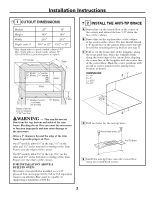
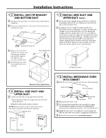
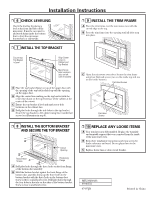
Installation Instructions ❒ 6 CHECK LEVELING Check the leveling by placing a level at the front and sides of the microwave. It may be necessary to add wood shims under the bottom duct to level the microwave front-to-back or side-to-side. ❒ 7 INSTALL THE TOP BRACKET ❒ 9 INSTALL THE TRIM FRAME A Place the trim frame over the microwave oven with the curved edge at the top. B Press the trim frame into the opening until all sides snap into place. Ensure that Top Bracket is Level Align Center Lines on Cabinet and Top Bracket Mark Screw Hole Locations (also on left side of bracket) A Place the top bracket flange on top of the upper duct with the opening of the top bracket lined up with the opening on the upper duct. B Align the center line marking on the top bracket with the center line drawn on the top front face of the cabinet at the center of the cutout. C Ensure the top bracket is level and mark screw hole locations on the cabinet face. D Drill pilot holes through the side holes in the top bracket. Secure the top bracket to the cabinet using four round-head screws (see illustration in step 8). C Open the microwave oven door. Secure the trim frame using four flat-head screws (two on the inside top and two on the inside bottom). Flat-Head Screws Flat-Head Screws ❒ 8 INSTALL THE BOTTOM BRACKET AND SECURE THE TOP BRACKET Cutout Opening Round-Head Screws Positioning Flange A Drill pilot holes through the three holes on the front flange of the bottom duct assembly. B Hold the bottom bracket against the front flange of the bottom duct assembly, lining up the three holes in the bottom bracket with the three holes in the bottom duct. Screw in three round-head screws. Drill pilot holes through the four holes in the tabs on the sides of the bottom bracket. Screw in four round-head screws. ❒ 10 REPLACE ANY LOOSE ITEMS A Your trim kit is now fully installed. Replace the turntable and turntable support that were removed from the inside of the microwave oven. B Keep these installation instructions and extra screws for future reference and need. Do not place them in the microwave oven. C Replace house fuse or close circuit breaker. MFL38268401 49-40552 07-07 JR Printed in China
-
 1
1 -
 2
2 -
 3
3 -
 4
4
 |
 |
