GE PGP989TNWW Use and Care Manual - Page 28
BLOWER ELECTRICAL, CONNECTIONS, CONNECTIONS cont., the enclosure with the screws removed earlier
 |
UPC - 084691172543
View all GE PGP989TNWW manuals
Add to My Manuals
Save this manual to your list of manuals |
Page 28 highlights
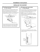
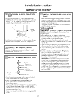
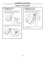
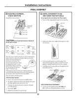
Installation Instructions INSTALLING THE COOKTOP 16 BLOWER ELECTRICAL CONNECTIONS • Loosen the two screws and remove and discard the sheet metal strap covering the 5-pin connector on the cooktop bottom. Save the screws for reinstallation later. 16 BLOWER ELECTRICAL CONNECTIONS (cont.) • Fold all wires into the electrical enclosure. Secure the enclosure with the screws removed earlier, making sure that no wires are trapped. 5-pin connectors Electrical enclosure Flexible conduit Remove screws and discard strap • Connect the 5-pin plug on the blower assembly to the matching 5-pin receptacle on the bottom of the cooktop. • Plug the cooktop cord set into a suitable electrical outlet. See step 17. 5-pin connectors 28
-
 1
1 -
2
-
3
-
4
-
5
-
6
-
7
-
8
-
9
-
10
-
11
-
12
-
13
-
14
-
15
-
16
-
17
-
18
-
19
-
20
-
21
-
22
-
 23
23 -
 24
24 -
 25
25 -
 26
26 -
 27
27 -
 28
28 -
 29
29 -
 30
30 -
 31
31 -
 32
32 -
 33
33 -
34
-
35
-
36
-
37
-
38
-
39
-
40
-
41
-
42
-
43
-
44
-
45
-
46
-
47
-
48
-
49
-
50
-
51
-
52
-
53
-
54
-
55
-
56
-
57
-
58
-
59
-
60
-
61
-
62
-
63
-
64
-
65
-
66
-
67
-
68
-
69
-
70
-
71
-
72
 |
 |

BLOWER ELECTRICAL
CONNECTIONS
•
Loosen the two screws and remove and
discard the sheet metal strap covering the 5-pin
connector on the cooktop bottom. Save the
screws for reinstallation later.
•
Connect the 5-pin plug on the blower assembly
to the matching 5-pin receptacle on the bottom
of the cooktop.
16
Installation Instructions
INSTALLING THE COOKTOP
28
BLOWER ELECTRICAL
CONNECTIONS (cont.)
•
Fold all wires into the electrical enclosure. Secure
the enclosure with the screws removed earlier,
making sure that no wires are trapped.
•
Plug the cooktop cord set into a suitable electrical
outlet. See step 17.
16
Remove screws
and discard strap
5-pin
connectors
Electrical
enclosure
Flexible
conduit
5-pin
connectors