GE PGS968SEPSS Quick Specs - Page 1
GE PGS968SEPSS Manual
 |
UPC - 084691199755
View all GE PGS968SEPSS manuals
Add to My Manuals
Save this manual to your list of manuals |
Page 1 highlights
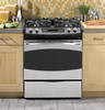
PGS968SEP GE Profile™ 30" Slide-In Gas Range Dimensions and Installation Information (in inches) Rear filler strip or backguard are available for these ranges Note: Door handle protrudes 3" from door face. Cabinets and drawers on adjacent 45° and 90° walls should be placed to avoid interference with the handle. 2-7/8" To Front Surface Of Countertop Note: Cabinets installed adjacent to slide-in ranges must have an adhesion spec of at least 194° temperature rating. Optional Kits for Slide-In Gas Ranges: (Available at additional cost) Lower/Side Trim Kits JXS56BB - Lower Trim Kit (Black) Accessory Backguards JXS32SS - Brushed-Chrome Accessory Backguard JXS37BB - Black Glass Accessory Backguard Rear Filler Strip WB07T10680 - Black Filler Strip Assembly 30" Slide-In Dimensions Range (in inches) Installation Information: Before installing, consult installation instructions packed with product for current dimensional data. 30" Min. For answers to your Monogram,® GE Profile™ or 15" Min. GE® appliance questions, visit our website at ge.com or call GE Answer Center® service, 800.626.2000. 30 4-1/2 6 5 2-1/4 Acceptable Electrical Outlet Area 30" Slide-in Elec. Range Accessory Backguard Fpaloatcellkronawagteiendsawtpriuptclhitainocnes 30″ Min. 24 30 31-1/4 Aug. 8, 2003 -km A* F9r-o1m/2″WMailnls. 2" (Grates) 30" Slide-In Range Dimensions (in inches) 20-5/8" 36 Door Clearance From Front Surface of Countertop FISBnouesrrtFfaOallaclpatetti&simoMLnueumTvshetel se 35f-rc3oo/4mu″nfttloeoro3t6ro-pt1o/2″ 23-3/16″ Mcr&3wine.oia5tcgtrexh″edar.pts,fdoedtprahreaplecoupwrnlogteeechkv,rebueoopnfxt f3csocr0ouafo″boromfikMvaniecnei nretghs. teoa db o t t o m 1Md3ea″pxt.h dbo18vios″etttraMohnmiencae.odvfferctorhatmbeicianathdel ejtascent Drawer IFfilyleoruDseaptCtrrhoieup2n5tN1″oe-(r1trOty/o4tpopB″iTcMtoaailpnu)c.osCkf oidgnuraungwteaertrrhtdoep: 7″ 30" Slide-in Elec. Range 3″ 9/16″ Aug. 8, 2003 -km Maintain 27-1/2** at least 6" 30"(eMxcliund.ing handle) from nearest *A - JXS37 is 5-1/4" ancdoJmXSb3u2sitsib4l"e 15" Min. 44-3/4 6 **Total depth from wall to surface. front of closed oven door including handle is 30-1/2. 31-1/2 15″ 2390--115/1/161″62″″MMaixn.. OAGEcualctesleceLpttritnAiacerbael&lea STWohidaCevl2eeCa3Roran-3it3s1roe-/1dl1/P8E6″adngeel 30 30 4-1/2 Counter Cutout Dimensions (in inches) 6 5 30" MIfiny. ou arS3e1h-a1Nv/e8ORWTaidiseuedCsoEinndtgrgoel tTPhoaenCelel ar Filler strip or Backguard: If you are using the Filler strip or Backguard: B 2-1/4 Acceptable 9/16 36 Electrical MOaiunttleatinArea at least 6" from nearest 23-3/16 30" Min. to unprotected cabinet from countertop 23-3/16 13" Max. *Wall to frocnot mofbustible 18" Min. 6closed door hsaurnfdalcee. on model JSP34. M2ax8. d-e1p/th4o*f 30 28" on models JSP26/J3S1S-12/26/16. cord, plug, 45-1/re8ceptacle box & gas hookup 30 25 Acceptable 35-7/8"-38" 3-1/2" to prevent interference Gas Line & Electrical from floor to with drawer All GE ranges aOre ueqtuleiptpeAd rweitah countertop 3 an Anti-Tip device. The installation If you are us7inogf thitshdeevice is an important, Note: below Rcoaunngteermtoapyifbteheplraacnegdewsiitdhe0t"ricmles1aa5rabnocvFeeil(tlhf1el2uersschot)ruiapnttoethrretBorobepfaqtuahcieerecrkdaxknsggtteeewpu. ninaadthrleldbinas:etanlyladtoionnsiddethweaclalsbinet fronts at least 1/4". (Self-clean combustible surface. m3236o90--d11e5/1/l16s6" "MoMnaixnly.. .) Maintain at least 6" distance from nearest 25 30 B is 9-1/2" from walls on either side for PS2Sp295e75c,iPfiGcSa97t5ion Created 5/09 and PGS908 and 6" for PGS968 230135 *Wall to front of
-
 1
1 -
 2
2
 |
 |
