GE PS968SPSS Installation Instructions - Page 2
Power Cord And Conduit Installa - electric range
 |
UPC - 084691197546
View all GE PS968SPSS manuals
Add to My Manuals
Save this manual to your list of manuals |
Page 2 highlights
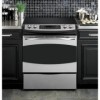
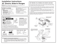
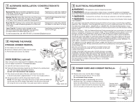
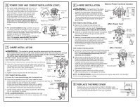
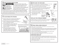
3 ALTERNATE INSTALLATION / CONSTRUCTION KITS Description: Use: Backguard Kit: Adds a decorative backguard to the rear of the range. This kit can only be used when the opening in the countertop is 25" deep. Designed to be used when replacing a free-standing range with a slide-in. Maintop Filler Kit: Adds a filler strip to the rear of the range. This kit can only be used when the opening in the countertop is 25" deep. This kit cannot be used with a backguard kit. Used to fill gap between the range back and wall. Body Side Kit: Contains a color-matched side panel which can be used to create a finished appearance on either side of the range. Designed to be used when cabinets are absent on one side of the range. Lower Trim Kit: Contains a color-matched toe kick and extra-long leveling legs. Designed to be used when the range needs to be raised higher than 36-1/2". Use kit when countertop height is 36-1/2" to 38" high. To order accessory kits, call 1.866.775.4557, or visit www.GEAppliances.com. 4 PREPARE THE RANGE STORAGE DRAWER REMOVAL A. Pull drawer out until it stops. B. Lift front of drawer until the stops clear the guide. C. Pull forward and remove the drawer. Protective channel Rail Guide DOOR REMOVAL (optional) Door removal is not a requirement for installation of the product but is an added convenience. To remove the door: A. Open the oven door as far as it will go. Stop Hinge slot Stop Hinge unlocked position B. Push both hinge locks down toward the door frame to the unlocked posi- Hinge tion. This may require a flat-blade screwdriver. arm DO NOT LIFT THE DOOR BY THE HANDLE! C. Place hands on both sides of the door, and close the oven door to the removal position. (Approximately 1"-2" from the closed position.) D. Lift door up and out until the hinge arms clear the slots. NOTE: The oven door is very heavy. Be sure you have a firm grip before lifting the oven door off the hinges. Use caution once the door is removed. Do not lay the door on its handle. This could cause dents or scratches. Hinge clears slot 5 ELECTRICAL REQUIREMENTS WARNING: This appliance must be properly grounded. WARNING: All new constructions, mobile homes, recreational vehicles and installations where local codes do not allow grounding through neutral require a 4-conductor, UL-listed range cord. WARNING: To prevent fire or shock, do not use an extension cord with this appliance. WARNING: To prevent shock, remove house fuse or open circuit breaker before begin- ning installation. We recommend you have the electrical wiring and hookup of your range connected by a qualified electrician. After installation, have the electrician show you how to disconnect power from the range. You must use a single-phase, 120/208 VAC or 120/240 VAC, 60 hertz electrical system. If you connect to aluminum wiring, properly installed connectors approved for use with aluminum wiring must be used. Effective January 1, 1996, the National Electrical Code requires that new construction (not existing) utilize a 4-conductor connection to an electric range. When installing an electric range in new construction, mobile home, recreational vehicle, or an area where local codes prohibit grounding through the neutral conductor, refer to the section on four-conductor branch circuit connections. Check with your local utilities for electrical codes which apply in your area. Failure to wire your oven according to governing codes could result in a hazardous condition. If there are no local codes, your oven must be wired and fused to meet the National Electrical Code, NFPA No. 70 - latest edition, available from the National Fire Protection Association. This appliance must be supplied with proper voltage and frequency and connected to an individ- ual, properly grounded, 40 amp (minimum) branch circuit protected by a circuit breaker or time-delay fuse. Use only a 3-conductor or a 4-conductor UL-listed range cord. These cords may be provided with ring terminals on wire and Rating plate a strain relief device. A range cord rated at 40 amps with 125/250 minimum volt range iiostpsrehenoqiunulgidrseb.deC. Aamr5ea0rskahemodupflodrrabunesgeteawkceoitnhrdtnoioscmneoinnttaerler1ct3oh⁄me8"mcdaeibanlmedeeadtne,drbcsuottrnaifninuescreetidloie,nf within the knockout hole to keep the edge from damaging the cable. Rating plate The rating plate is located on the oven frame or on the side of the drawer frame. 6 POWER CORD AND CONDUIT INSTALLA- TION A. Remove wire cover (on the back of range) by removing screws using a 1/4" nut driver. Do not discard these screws. B. For power cord and 1" conduit only, remove the knockout ring (13⁄8") located on bracket directly below the terminal block. To remove the knockout, use a pair of pliers to bend the knockout ring away from the bracket and twist until ring is removed. Terminal block (appearance may vary) Knockout ring in bracket Knockout ring removed Wire cover
-
 1
1 -
 2
2 -
 3
3 -
 4
4
 |
 |