GE PT956SRSS Installation Instructions - Page 2
Warning - installation manual
 |
UPC - 084691223696
View all GE PT956SRSS manuals
Add to My Manuals
Save this manual to your list of manuals |
Page 2 highlights
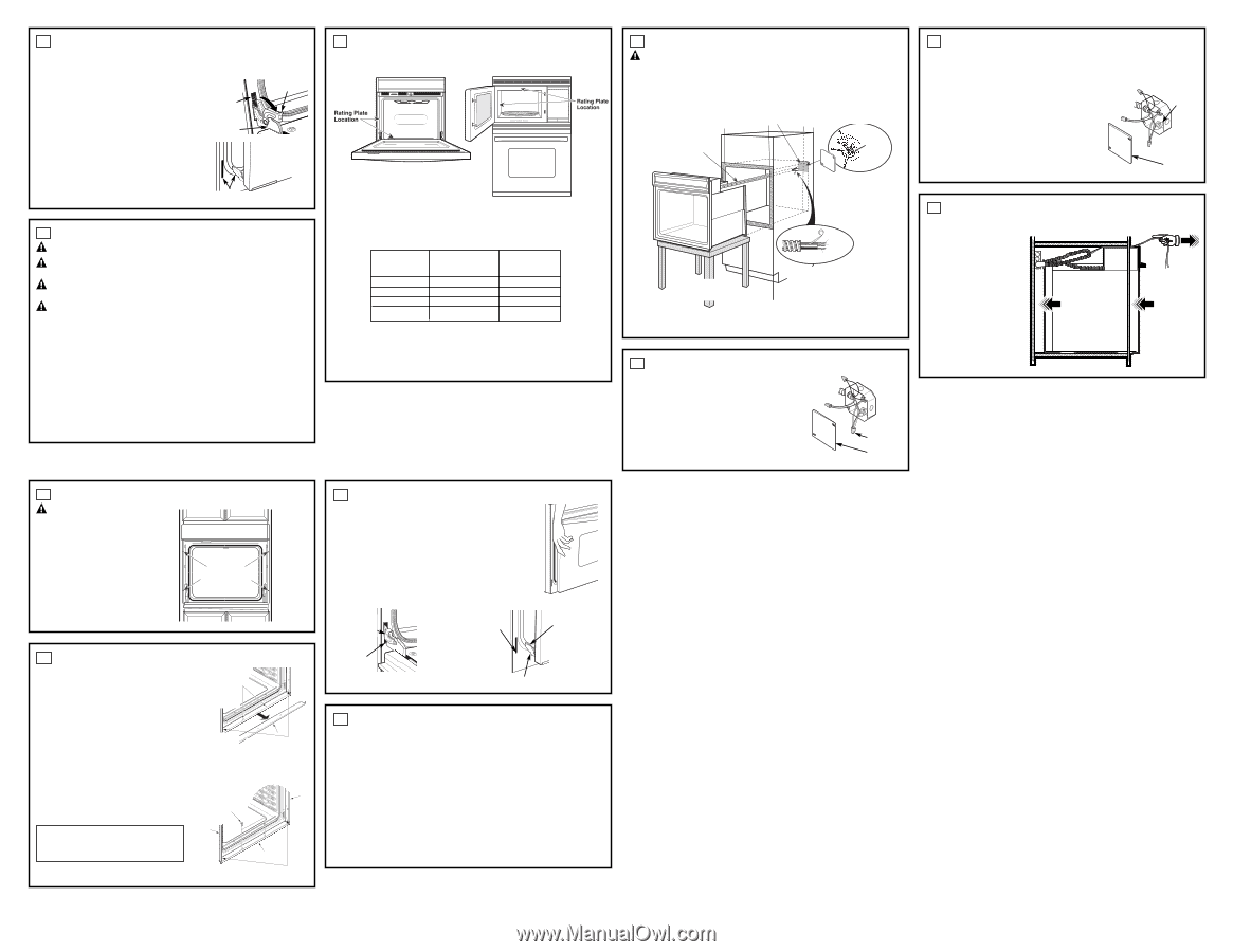
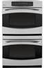
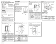
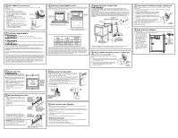
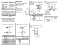
3 DOOR REMOVAL (recommended) NOTE: Door removal is not a requirement for installation of the product but is an added convenience. To remove the door: A. Open the oven door as far as it will go. B. Push both hinge locks down toward the door frame to the unlocked position. This may require a flat-blade screwdriver. DO NOT LIFT THE DOOR BY THE HANDLE! Hinge Slot Hinge Unlocked Position C. Place hands on both sides of the door and close the oven door to the removal position (approximately 1"-2" [2.5 cm-5.1 cm] from the closed position). Hinge Arm D. Lift the door up and out until the hinge arms clear the slots. NOTE: The oven door is very heavy. Be sure you have a firm grip before lifting the oven door off the hinges. Use caution once the door is removed. Do not lay the door on its handle. This could cause dents or scratches. Hinge Clears Slot 4 ELECTRICAL REQUIREMENTS WARNING: This appliance must be properly grounded. WARNING: To prevent fire or shock, do not use an extension cord with this appliance. WARNING: To prevent shock, remove house fuse or open circuit breaker before beginning installation. WARNING: Improper connection of aluminum house wiring to copper leads can result in an electrical hazard or fire. Use only connectors designed for joining copper to aluminum and follow the manufacturer's recommended procedure closely. We recommend you have the electrical wiring and hookup of your appliance connected by a qualified electrician. After installation, have the electrician show you how to disconnect power from the appliance. You must use a single-phase, 120/208 VAC or 120/240 VAC, 60 Hertz electrical system. If you connect to aluminum wiring, properly installed connectors approved for use with aluminum wiring must be used. Effective January 1, 1996, the National Electrical Code requires that new construction (not existing) utilize a four-conductor connection to an electric oven. When installing an electric oven in new construction, a mobile home, recreational vehicle or an area where local codes prohibit grounding through the neutral conductor, refer to the section on four-conductor branch circuit connections. Check with your local utilities for electrical codes which apply in your area. Failure to wire your oven according to governing codes could result in a hazardous condition. If there are no local codes, your oven must be wired and fused to meet the National Electrical Code, NFPA No. 70 - latest edition, available from the National Fire Protection Association. 4 ELECTRICAL REQUIREMENTS (CONT.) This appliance must be supplied with the proper voltage and frequency and connected to an individual, properly grounded branch circuit, protected by a circuit breaker or fuse. See the rating plate located on the oven frame to determine the rating of the product. Rating plate is located on the oven side trim, side front frame or lower front frame. Rating plate is located on the microwave oven inside wall or upper front frame. Use the chart below to determine the minimum recommended dedicated circuit protection: KW Rating 240V ≤4.8 KW 4.9 KW-7.2 KW 7.3 KW-9.6 KW 9.7 KW-12.0 KW KW Rating 208V ≤4.1 KW 4.2 KW-6.2 KW 6.3 KW-8.3 KW 8.4 KW-10.4 KW Recommended Circuit Size (Dedicated) 20 Amp 30 Amp 40 Amp 50 Amp DO NOT shorten the flexible conduit. The conduit strain relief clamp must be securely attached to the junction box and the flexible conduit must be securely attached to the clamp. If the flexible conduit will not fit within the clamp, do not install the oven until a clamp of the proper size is obtained. The 3 power leads supplied with this appliance are suitable for connection to heavier gauge household wiring. The insulation of these 3 leads is rated for temperatures much higher than the temperature rating of the household wiring. The current-carrying capacity of the conductor is governed by the wire gauge and the temperature rating of the insulation around the wire. 5 MAKE ELECTRICAL CONNECTIONS WARNING: Switch power off at the service panel and lock the service disconnecting means to prevent power from being switched on accidentally. When the service disconnecting means cannot be locked, securely fasten a prominent warning device, such as a tag, to the service panel. Place oven on table or platform even with the cutout opening. For a single oven, the platform must support 200 lbs. (91 kg); and for a double oven, the platform must support 375 lbs. (170 kg). Connect the flexible conduit to the electrical junction box as shown below*. Position the conduit in such a manner that it will lie on top of the oven in a natural loop when the oven is installed. You will need to purchase an appropriate strain relief clamp to complete the connection of the conduit to the junction box. Junction Box Conduit Ground Wire Place Oven on a Support to Assist in Connecting Conduit Bare Ground Red White Black Strain Relief Clamp (not included) Must Be Used at Junction Box *Ovens come equipped with a 48" long conduit. If a longer conduit is desired, there may be one available for your model. To check availability or order parts, call 1.800.GE.CARES. 6 THREE-CONDUCTOR BRANCH CIRCUIT CONNECTION NOTE: If residence leads are aluminum conductors, see WARNING in Section 4, Electrical Requirements. When connecting to a three-conductor branch circuit, if local codes permit: A. Connect the bare oven ground conductor with the crimped neutral (white) lead to the branch circuit neutral (white or gray in color), using a wire nut. B. Connect the oven red lead to the branch circuit red lead and the oven black lead to the branch circuit black lead in accordance with local codes, using wire nuts. C. Install junction box cover. Ground and Neutral Wires Junction Box Cover 7 FOUR-CONDUCTOR BRANCH CIRCUIT CONNECTION NOTE: If residence leads are aluminum conductors, see WARNING in Section 4, Electrical Requirements. A. Cut the neutral (white) lead from the crimp. Re-strip the neutral (white) lead to expose the proper length of conductor. B. Attach the appliance grounding lead (green or bare copper) in accordance with local codes. If the residence grounding conductor is aluminum, see WARNING in Section 4. C. Connect the oven neutral (white) lead to the branch circuit neutral (white or gray) in accordance with local codes, using a wire nut. Ground Wire D. Connect the oven red lead to the branch circuit red lead and the oven black lead to the branch circuit black lead in accordance with local codes, using wire nuts. NOTE: If the residence red, black or white leads are aluminum conductors, see WARNING in Section 4. E. Install junction box cover. Junction Box Cover 8 SLIDE OVEN INTO OPENING A. Loop (do not tie) a 36" (91 cm) string around the conduit before the oven is slid into place. This will keep the conduit from falling behind the oven. B. Lift oven into cabinet cutout using the oven opening as a grip. Carefully push against oven front frame. Do not push against outside edges. C. As you slide the oven back, pull the string so that the conduit will lie on top of the oven in a natural loop. D. When you are sure the conduit is out of the way, slide the oven ¾ way back into the opening. Remove the string by pulling on one end of the loop. Pull Out on String Loop While Pushing the Oven Into the Cabinet 9 MOUNT THE OVEN WARNING: Mounting screws must be used. Failure to do so could result in the oven falling out of the cabinet, causing serious injury. NOTE: Before drilling the pilot holes, make sure the oven is pushed as far back into the opening as it will go and is centered. NOTE: If the cabinet is particle board, you must use #8 x ¾" particle board screws. These may be purchased at any hardware store. A. Drill through the mounting holes (top and bottom) of the side trim for the #8 mounting screws provided. B. Secure the oven cabinet with the screws provided. Mounting Hole Locations (hole locations may vary) The Screws Must Be a Minimum of 1/4" (6 mm) From the Front of the Cutout. 11 REPLACING THE OVEN DOOR NOTE: The oven door is heavy. You may need help lifting the door high enough to slide it into the hinge slots. Do not lift the door by the handle. A. Lift the oven door by grasping each side. B. With the door at the same angle as the removal position (approximately 1"-2" [2.5 cm-5.1 cm] from the closed position), seat the notch of the hinge arm into the bottom edge of the hinge slot. The notch of the hinge arm must be fully seated into the bottom of the slot. C. Fully open the door. If the door will not fully open, the indentation is not seated correctly in the bottom edge of the slot. D. Push the hinge locks up against the front frame of the oven cavity, to the locked position. E. Close the oven door. Hinge in Locked Position Bottom Edge of Slot Hinge Arm 10 BOTTOM TRIM INSTALLATION A. With oven installed, take the bottom trim and center it on the bottom front edge of the cabinet opening. B. Using the trim as a template, mark the center of each slot (two total) where the mounting holes will be drilled. For 27" (68.6 cm) Models with Lower Trim in Position, Mark (2) Mounting Hole Locations Here C. Remove the trim. D. Drill pilot holes into the center of each template mark. Remove Lower Trim Before Predrilling Mounting Holes For 30" (76.2 cm) Models with Lower Trim in Position, Mark (2) Mounting Hole Locations Here E. Place the bottom metal trim centered over the predrilled mounting holes. Tape the edges of the trim down to maintain the alignment. Trim Screw Locations for 27" (68.6 cm) Models F. Using two trim screws provided, secure the bottom with Lower Trim trim to the bottom edge of the cabinet. IMPORTANT: If this unit is ever removed from the cabinet or the oven is ever pulled out for service, the bottom trim must be removed first or damage to the trim will occur. Side Trim Metal Lower Trim Side Trim Trim Screw Locations for 30" (76.2 cm) Models with Lower Trim Notch of Hinge Securely Fitted Into Bottom of Hinge Slot Hinge Notch 12 FINAL INSTALLATION CHECKLIST • Check to make sure the circuit breaker is closed (RESET) or the circuit fuses are replaced. • Be sure power is in service to the building. • Check that all packing material and tape have been removed. Failure to remove these materials could result in damage to the appliance once the appliance has been turned on and surfaces have heated. • Remove all items from inside the oven. • Check to be sure that the mounting screws are installed and flush with the side trim (see Section 9). • Check that the bottom trim is installed properly (see Section 10). OPERATION CHECKLIST • Turn on the power to the oven (refer to your Owner's Manual). Verify that the bake and broil units and all cooking functions operate properly. • See your Owner's Manual for the troubleshooting list. • Be sure all of the oven controls are OFF before leaving the oven.
-
 1
1 -
 2
2 -
 3
3 -
 4
4
 |
 |