GE PW9000DFBB Quick Specs - Page 1
GE PW9000DFBB Manual
 |
View all GE PW9000DFBB manuals
Add to My Manuals
Save this manual to your list of manuals |
Page 1 highlights
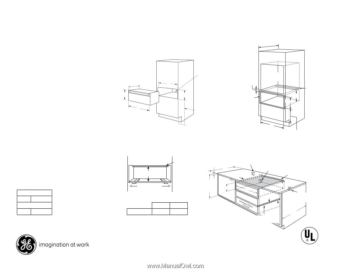
PW9000DF 23-1/2" min. 23-1/2" min. GE Profile™ Series 30" Warming Drawer Locate electrical outlet in adjacent Locate electricaUl nder Oven Installation cabinet 16" from left side or 42" outlet in adjacent 23-1/2" min. Dimensions and Installation Information (in inches) from right side Locate electrical Optional Accessories: ZXD30B -1/4" panel kit capability. Warming Drawer Dimensociauobtlnientesitn1a6d"jafrcoemnt 23-1/4" A left side or 42" Note: Custom panel will not be flush with adjacent from right side cabinet 16" from left side or 42" from right side Locate electrical outlet in adjacent cabinet 16" from cabinetry drawers and doors. left side or 42" 10-1/2" 23-1/4" Undercounter Installation: A solid barrier m2u3-s1t/4" 9-1/4" A A from right side 2" min. 23-1/2" min. Oven cutout Oven cutout 2x2 or 2x4 anti-tip block against rear wall 9" from flo2ox2r toor b2xo4ttom Oven cutout be installed at least 1" from the lowest point of the bottom cutout. Uosfecoaonkytosoplibdumrnaetrebrioaxl stuoct1hh0ea-1s1t0o/-112pB//4"2o""f-tthhieck plywood. Allow at least 1/4" air gap between the barrier and the top of the warming drawer. See B label on top of the warming drawer for approved 23-1/4" 10-1/2" B 24" A recommended 9-1/f4ro" m floor 9-1/4" for under 9-1/4" countert2o4p" installatrioencommended from floor for under 242" 4" recommended frormecflooomr mended Allow 5/8" 2" min. overlap on all sides 2" min. Allow 5/8" overlap on Allow 5/8" all sides overlap on all sides cooktop models. B countertop installation fcoofrurunontemdretropfloor infsotarllautionnder A Under Oven Installation: Additional clearance between cutouts may be required. Check to be sure that oven supports above the warming Install 2x4 or 2x2 anti-tip countertop installation A drawer location do not obstruct the required 9" block 9" Install Install interior 23-1/2" depth and 9-1/4" height. Door handle protrudes 2-3/4" from door face. 2x4 or 2x2 runners or solid9" from floo2rx4 or 2x2 to bottomanti-tip 9" of block block 9" 2x4 or 2x2 anti-tip block 9" from floor Undercounter Installation Oven 9" 9-1c/u4t"out 9" 2ofaa"bngmtlaoi-incitniskp2t.xbr2elooacrrk2x4 wfloaollr9t"oaawfngabrtaoloil-imn9ttits"potfbrmroelomacrk of blocflkoor to bottom 9-1/4"Allow 59/" 8" of block ov9e-1r/4la" p on all sides 1" min. above toekick oAr adjust to oven installation height 1" min. a1b"omvien.taobeokviecktoekick or adjusot rtoadojuvsetnto oven installatiionsntahlleaitgiohntheight A Cabinets and drawers on adjacent 45° and 90° bottom walls should be placed to avoid interference with(Must 2x4 or 2x2 Supporut n1n5e0rslbosr.)solid the handle. bottom from2fxl4ooorr 2x2 to bottom to rbuontnteorms or solidInstoaf lbllock of blocbkottom 2x4 or 2x2 (Must Support 150albns.t)i-tip Installation Information: Before installing, consult (Must Support 1509lb"s.) block 9" installation instructions pacDkeimd wenitshiopnrosd(uinctinfocrhes) current dimensional data. Dimensions (in inches) 2x4 or 2x2 from floor to bottom KW Rating 120V .45 Dimensions (in inAches) ruBnners or soAlid 27" Drawer 25-1/2" 27" DrAawe2r 6-3/4b" ottoB2m5-1/2" of bBlock 26-3/4" Breaker Size (Must Support 1A50 lbs.) B 120V 15 Amps 27" Drawer 25-1/2" 30" Draw3e0r" Draw2e6r-32/482"-18/-21" /2" 2299--33//44" " Electrical outlet 1-1/2" Cabinet top 25" 1-1/2" Cabinet top 42" max. from ElEelcetrcictrailcoaultloetutlet 2Ibn5es"ltoarw1Clilg-aaa1bh/sci2onot"loeiE4rdktsil2gtbteoioad"hpcprremttiers2riaci5dx"ae.l forIbnoeusltomat4rwllil2gefc7aal"hstacuoomtlobsidksEfchtabioilnadaulpxerwree.bsiecfhrtiritntor7hweimc"tiastm7hild"oaEfc7semluaulixedtbos.calehieftnxrtwoei.ctfiat7hl Iarf"onlsemounisdaIatontatlenreiaxrs-totc.ttltiilaf-aopt2lbilpbxb2i4noIarflxbnoleonet4lsaocototttroirkaor-cwctmltrk2ilaaop2a2xabgbxbox2ligla4nol2of9aetioctnbti"orknswlmf2osatraxtcgoo2llakmf9inb"slfotrcokm 36" Countertop 1" Min*. 36" Install Countebretloowp a a scooloidk1tb"oMaprinri*.er 7 rear cabinet wall 9" from 9 floo9r to bottom of block height 36" 9-1/4" height 1" Min*. A 9-1/4" A Countertop height 9-1/4" A Solid barrier Electrical outlet 9 Solid barrier Electrical Electrical outlet 16" max. outlet 16" mfroamxl.eft side 1-1/1/2S4o"liAdirbagrarpier Cabinet top 1/4" Air gap fr4oEm2le"cletrmfitcasaildex. from right side outlet 16" max. from23-le1/f2t"smidine. Electrical out flush with sid 25" 1/4In" Astiragllaapsolid ba2rr3ie-1r/2" min. below a cooktop cabinet 7" m 30" Drawer 28-1/2" 29-3/4" 30" Drawer 28-1/2" 29-3/4" Dimensions (in inches) aFoprpaliannswceeqrsuteostyioonusr,MviosAnitoogurrawme®bosritGeEa®t B Install a solid barrier below a cooktop Install a solid barrier 2In3-s1t/a2l"lmains.olid barrier below a cooktop below a cooktop 36" 1" Min*. Countertop height 9-1/4" A 7 Listed by Underwriters Laboratories geappliances.com or call GE Answer Center® Solid barrier 27" Draweserrvice, 800.626.202050-. 1/2" 26-3/4" Specification Created 2/13 221131 1/4" Air gap
-
 1
1 -
 2
2
 |
 |