GE PW9000SFSS Quick Specs - Page 1
GE PW9000SFSS Manual
 |
View all GE PW9000SFSS manuals
Add to My Manuals
Save this manual to your list of manuals |
Page 1 highlights
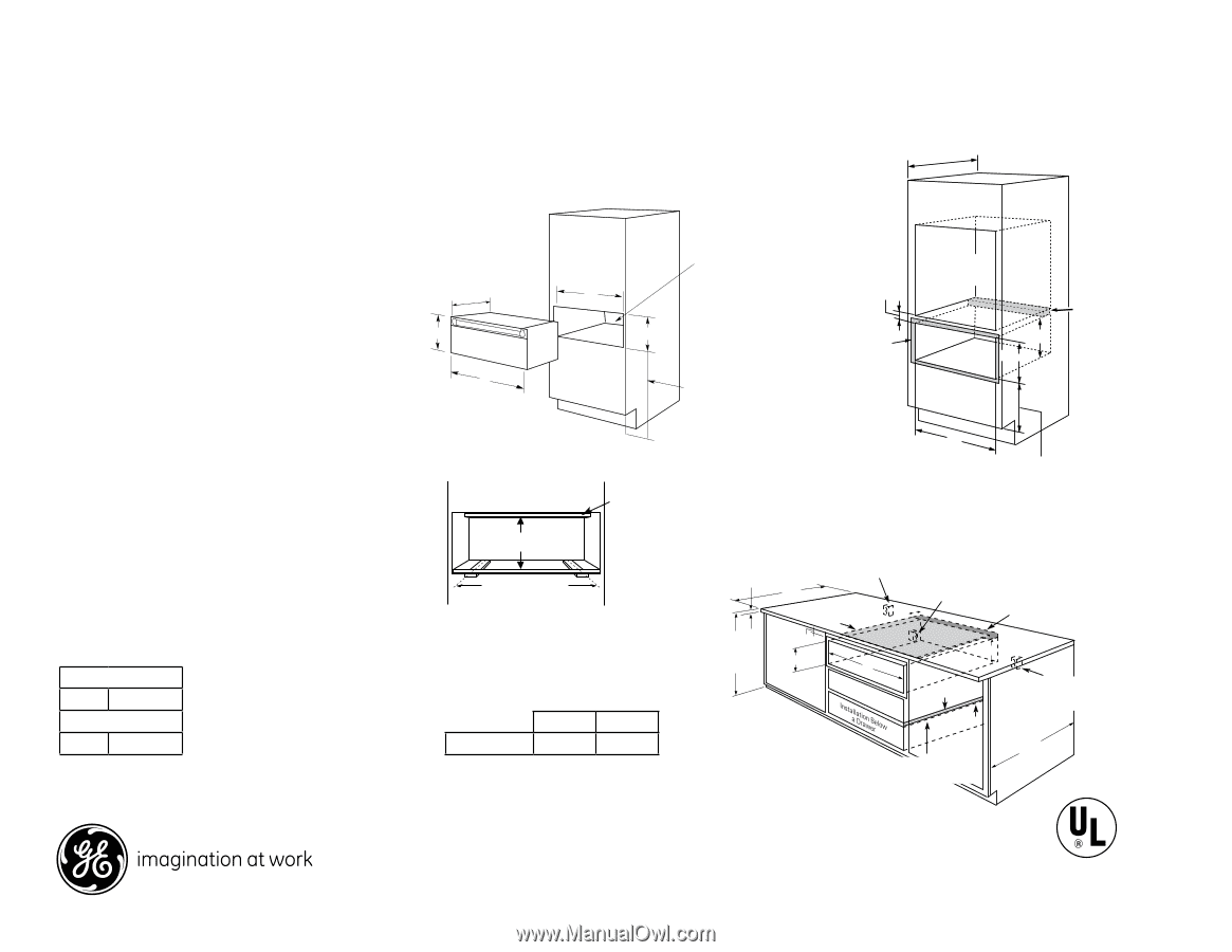
23-1/2" min. Locate electrical PW9000SF GE Profile™ Series 30" Warming Drawer Locate electrical outlet in adjacent cabinet 16" from outlet in adjacent cabinet 16" from 23-1/2" min. left side or 42" from right side Under Oven Installation left side or 42" 23-1/2" min. Dimensions and Installation Information (in inches) from right side Locate electrical Optional Accessories: capability. ZXD30B -1/4" panel k2i3t -1/4" 23-1/4" Note: Custom panel will not be flush with adjacent cabinetry drawers and doors. 10-1/2" 10-1/2" Undercounter Installation: A solid barrier m2u3-s1t/4" Warming DrawerADimensociauobtlnientesitn1a6d"jafrcoemnt A left side or 42" Locate electrical from right side outlet in adjacent cabinet 16" from 9-1/4" A 9-1/4" left side or 42" from right side 2" min. 23-1/2" min. Oven cutout Oven cutout 22axn"2tmi-otiripn2b.xl4ock against rear wall 9" from flo2ox2r toor b2xo4ttom be installed at least 1" from the lowest point of the bottom of cooktop burner box to the1t0o-1pB/2o"f the cutout. Use any solid material such as 1/4"-thick B plywood. Allow at least 1/4" air gap between the barrier and the top of the warming drawer. See B 23-1/4" 10-1/2" 24" A recommended 9-1/f4ro" m floor for under 9-1/4" countert2o4p" installatrioencommended from floor 24" recommended from floor for under 2re4cc"oomumnetnederdtop Allow 5/8" 2" min. overlap on all sides 2" min. Allow 5/8" overlap on Allow 5/8" all sides overlap on Oven9A"llow 5o/fa8bntl"oi-ctikp block 9-1c/u4t"ouoat vl9l"esridlaepsawfoloofgaobanllrlion9tcs"o2aawftlkfoxngabrr2otaoleoilr-iomna9tttirts"oprot2fbbrmrxoeol4omatctrokm 9-1/4" 9" of block 9-1/4" label on top of the warming drawer for approved cooktop models. Under Oven Installation: Additional clearance B for under froinmsfltoaorllation countertop for under installation countertop installation all sides A 1" min. above toekick between cutouts may be required. Check to be sure that oven supports above the warming drawer location do not obstruct the required interior 23-1/2" depth and 9-1/4" height. Door handle protrudes 2-3/4" from door face. 9" 2x4 or 2x2 runners or solid9" Install 2x4 or 2x2 anti-tip block 9" Install from floo2rx4 or 2x2 to bottomanti-tip 9" of block block 9" InstI2anxs4ltlaollr 2x2 2x4aontri-t2ipx2 antibf-rlootmcipkf9lo"or Undercounter Installation A oAr adjust to oven installation height 1" min. a1b"omvien.taobeokviecktoekick or adjusot rtoadojuvsetnto oven installatiionsntahlleaitgiohntheight Oven cutout A Cabinets and drawers on adjacent 45° and 90° bottom 9" walls should be placed to avoid interference with(Must 2x4 or 2x2 Supporut n1n5e0rslbosr.)solid from2fxl4ooorr 2x2 bloctokbo9t"tom to of rbbulonotnctbeokormtstoomr solidfromof block floor the handle. bottom2x4 or 2(Mxu2st Support 150tlobs.b) ottom Installation Information: Before installing, consult installation instructions pacDkeimd wenitshiopnrosd(uinctinfocrhes) current dimensional data. (Must Supprourtn1n5e0rlbsso.) r solid of block bottom Dimensions (in inches) (Must Support 150 lbs.) KW Rating Dimensions (in inAches) B A B 120V .45 Breaker Size 120V 15 Amps 27" Drawer 25-1/2" 27" DrAawe2r 6-3/4" B25-1/2" A Di2m7" eDrnawseirons (in in320c5"-Dh1r/ae2w3"se0r)" Draw2e6r-32/482"-18/-21"/2" 26-3/4" B 2299--33//44" " Electrical outlet 1-1/2" Cabinet top 25" 1-1/2" Cabinet top 42" max. from ElEelcetrcictrailcoaultloetutlet 2Ibn5es"ltoarw1Clilg-aaa1bh/sci2onot"loeiE4rdktsil2gtbteoioad"hpcprremttiers2riaci5dx"ae.l forIbnoeusltomat4rwllil2gefc7aal"hstacuoomtlobsidksEfchtabioilnadaulpxerwree.bsiecfhrtiritntor7hweimc"tiastm7hild"oaEfc7semluaulixedtbos.calehieftnxrtwoei.ctfiat7hl Iarf"onlsemounisdaIatontatlenreiaxrs-totc.Ettltiilaf-aoplt2lebilpbxb2ic4noIarflxbnoletonet4lsaocrototttroiirkaor-ccwctmltrk2ilaaopa2a2xabgbxbox2lligla4nol2ofo9aetioctnbti"ourknswlmf2osattraxtcgolo2lelakmf9itnb"slfotrcokm 36" Countertop height 36" 1" Min*. 36" Install Countebretloowp a a scooloidk1tb"oMaprinri*.er 9-1/4" height 1" Min*. A 9-1/4" Countertop height 9-1/4" A 7 1-1/2" 9 CabiAnet top rea4r 2ca"bmineat xw.afllr9o"mfrom floor9rigtohbtosttiodmeof block Electrical out flush with sid Solid barrier 259" Solid barrier Electrical Electrical outlet 16" max. outlet 16" mfroamxl.eft side cabinet 7" m Instfarollma sleofltidsibdaerrier 1/4" Air gapbelowElaecctoriockatlop 7 1/S4o"liAdirbagrarpier outlet 16" max. from23-le1/f2t"smidine. 3C6o"unterto1p/4Ibn"eAsltoirawgllaaaps1coo"loiMdktbionap2*.rr3ie-1r/2" min. 30" Drawer 28-1/2" 29-3/4" 30" Drawer 28-1/2" A 29-3/4" B Ibnehsltoeawlilgaahsctooloidktboaprrier 9-1/4" 23-1/2" min. A Install a solid barrier below a cooktop Listed by Solid barrier 27" DraweForr answers to you2r5M-o1n/2o"gram® or GE2®6-3/4" Underwriters Laboratories appliance questions, visit our website at 1/4" Air gap geappliances.com or call GE Answer Center® service, 800.626.2000. 30" Drawer 28-1/2" 29-3/4" Specification Created 2/13 221135 Install a solid barrier below a cooktop
-
 1
1 -
 2
2
 |
 |