GE WSM2700WWW Installation Instructions - Page 6
Installation Instructions, WARNING
 |
View all GE WSM2700WWW manuals
Add to My Manuals
Save this manual to your list of manuals |
Page 6 highlights
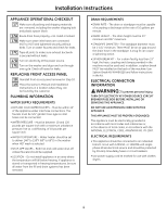
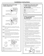
Installation Instructions CONNECTING APPLIANCE USING 4-WIRE CONNECTION CONNECTING APPLIANCE USING 4-WIRE CONNECTION (CONT.) CAUTION: Be sure electricity is OFF at power source (circuit breaker/fuse box). 8 Plug power cord into electrical outlet. 9 Return to Step 15 on page 3. NOTE: THIS APPLIANCE IS NOT APPROVED FOR 120-VOLT OPERATION. 1 Remove the terminal block access cover. 2 Install UL-listed 30A, 4-conductor NEMA 14-30- type ST closed loop terminal power cord and the strain relief. 3 Connect the green ground wire of the power cord to the terminal block bracket with the green grounding screw. 4 Connect the white wire from the power cord and the green ground wire from the appliance harness to the center (silver-colored) terminal of the terminal block. 5 Connect the black and red wires from the power cord to the two outer terminals of the terminal block. Green conductor Silver terminal Green ground screw Terminal block (14-30R) 4-wire receptacle Green ground wire Red wire Black wire White wire 6 Check all connection screws to make sure they are securely tightened. 7 Reinstall the terminal block access cover. EXHAUST INFORMATION WARNING - To reduce the risk of fire or personal injury: • This clothes dryer must be exhausted to the outdoors. • Use only 4″ rigid metal ducting for the home exhaust duct . • Use only 4″ rigid metal or UL-listed flexible metal (semi-rigid or foil-type) duct to connect the dryer to the home exhaust duct. It must be installed in accordance with the instructions found in "Connecting the Dryer to House Vent" on page 7 of this manual. • Do not terminate exhaust in a chimney, a wall, a ceiling, gas vent, crawl space, attic, under an enclosed floor, or in any other concealed space of a building. • Never terminate the exhaust into a common duct with a kitchen exhaust system. A combination of grease and lint creates a potential fire hazard. • Do not use duct longer than specified in the exhaust length table. Longer ducts can accumulate lint, creating a potential fire hazard. • Never install a screen in or over the exhaust duct. This will cause lint to accumulate, creating a potential fire hazard. • Do not assemble ductwork with any fasteners that extend into the duct. These fasteners can accumulate lint, creating a potential fire hazard. • Do not obstruct incoming or exhausted air. • Provide an access for inspection and cleaning of the exhaust system, especially at turns and joints. Exhaust system shall be inspected and cleaned at least once a year. • Remove and discard existing plastic or metal foil duct and replace with UL-listed duct. • Remove any lint from the wall exhaust opening. Internal duct opening Wall Check that exhaust hood damper opens and closes freely. 6
-
 1
1 -
 2
2 -
 3
3 -
 4
4 -
 5
5 -
 6
6 -
 7
7 -
 8
8
 |
 |
