Genie QuietLift 800 Owner's Manual - Page 15
Wall Control Installation - garage door parts
 |
View all Genie QuietLift 800 manuals
Add to My Manuals
Save this manual to your list of manuals |
Page 15 highlights
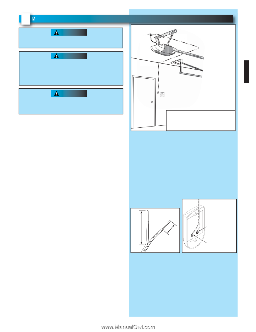
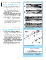
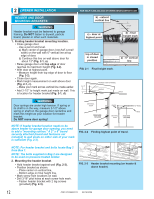
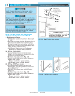
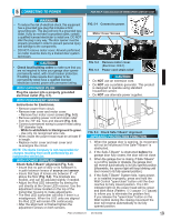
3 WALL CONTROL INSTALLATION WARNING Verify there is NO power to the opener before installing Wall Control wires and Wall Control. CAUTION Staples which are too tight can cut or pinch wires. Cut or pinched wires can cause the Wall Control to stop working. When using the insulated staples, make sure you fasten them only as tightly as needed to hold the wire snugly. WARNING Use of any other wall control can cause the door to operate unexpectedly and the light not to work. Use only the included Wall Control. NOTE: For Wall Control, wire and insulated staples locate Bags 6 and 7 from Box 2. 1. Wall Control location. • Wall Control location should be in direct sight of door. • It should be at least five feet (5') above floor to prevent small children from operating door. • It must be away from any moving parts. (You should NOT be able to reach the garage door while standing at Wall Control.) • Wall Control board screw connections are polarized, (+) positive and (-) negative. 2a. Wiring (If pre-wired). • Locate Wall Control pre-wired wire ends (Fig. 3-1). (They should be located within the guidelines mentioned above.) • Split and strip ends of wire (Fig. 3-2). • Fasten wire to Wall Control board screws on back of Wall Control. - Striped wire to the + (plus) terminal. - White wire to the - (minus) terminal. 2b. Wiring (If NOT pre-wired). • Pick a convenient location for mounting Wall Control using the guidelines mentioned above (Fig. 3-1). • Run wire from power head to Wall Control (Fig. 3-1). • Split and strip ends of wire (Fig. 3-2). • Fasten wire to Wall Control board screws on back of Wall Control. - Striped wire to the + (plus) terminal. - White wire to the - (minus) terminal. FOR HELP-1.800.354.3643 OR WWW.GENIECOMPANY.COM Wire from power head to Wall Control WCoanlltrol Separate entry door "wEanrtnrianpgmlaebnet"l EXAMPLE ONLY! This is an example of wire routing when NOT pre-wired. Your wire routing may be different. FIG. 3-1 Wall Control wire routing or White 2" - 1/2" + or BStlaricpked FIG. 3-2 Splitting and stripping. PN# 37026500123 05/15/2009 15
-
 1
1 -
2
-
3
-
4
-
5
-
6
-
7
-
8
-
9
-
 10
10 -
 11
11 -
 12
12 -
 13
13 -
 14
14 -
 15
15 -
 16
16 -
 17
17 -
 18
18 -
 19
19 -
 20
20 -
21
-
22
-
23
-
24
-
25
-
26
-
27
-
28
-
29
-
30
 |
 |