Gigabyte B650 AERO G User Manual - Page 25
CPU_LED CPU Cooler LED Strip/RGB LED Strip Header, SATA3 0/1/2/3 SATA 6Gb/s Connectors
 |
View all Gigabyte B650 AERO G manuals
Add to My Manuals
Save this manual to your list of manuals |
Page 25 highlights
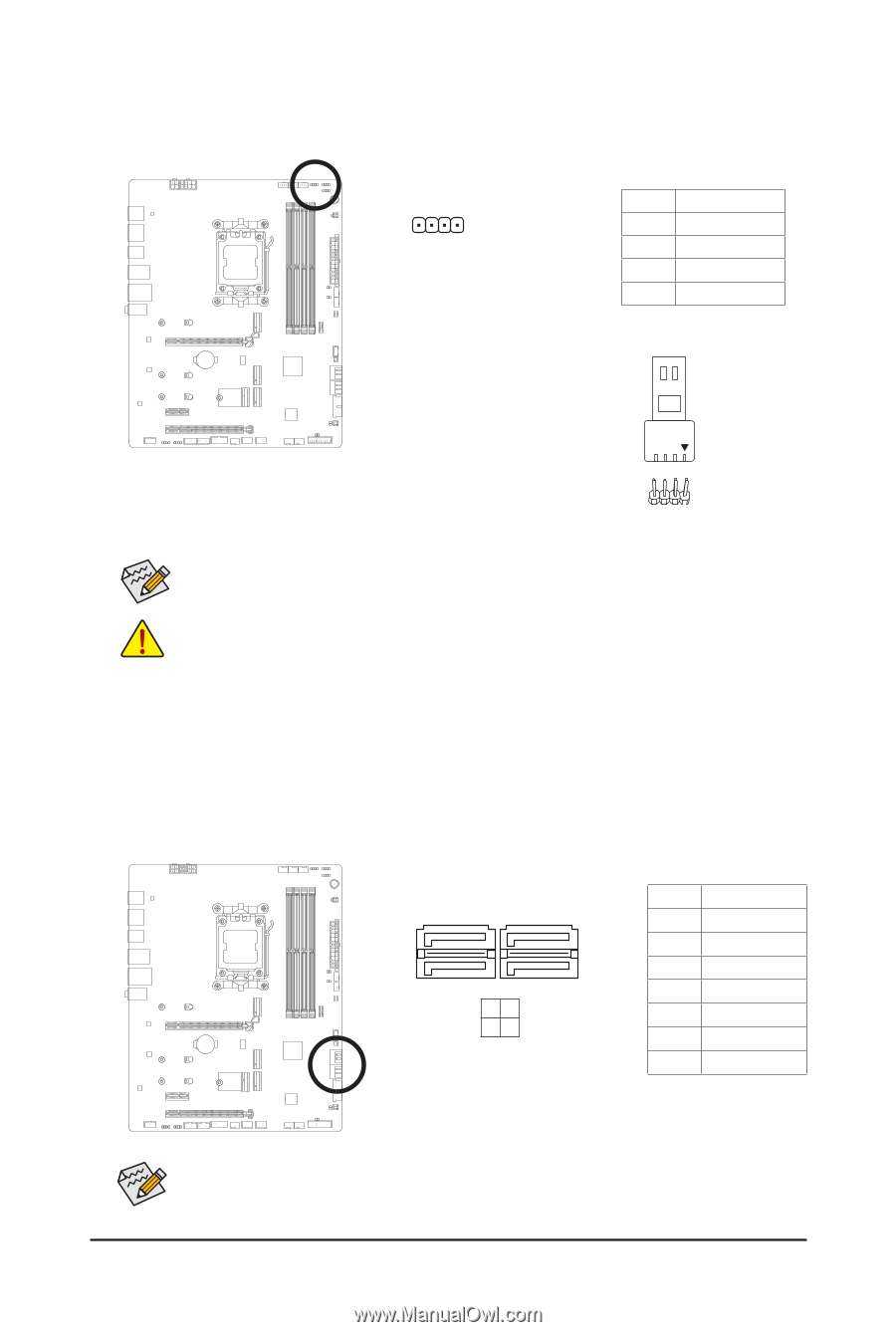
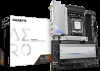
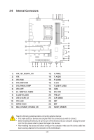
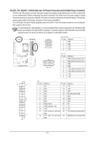
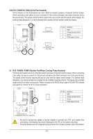
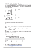
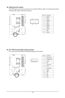
10) CPU_LED (CPU Cooler LED Strip/RGB LED Strip Header) The header can be used to connect a CPU cooler LED strip or a standard 5050 RGB LED strip (12V/G/R/B), with maximum power rating of 2A (12V) and maximum length of 2m. Pin No. Definition 1 1 12V 2G 3R 4B Connect the CPU cooler LED strip/ RGB LED strip to the header. The power pin (marked with a triangle on the plug) of the LED strip must be connected to Pin 1 (12V) of this header. Incorrect connection may lead to the damage of the LED strip. LED Strip 1 12V For how to turn on/off the lights of the LED strip, please navigate to the "Unique Features" page of GIGABYTE's website. Before installing the devices, be sure to turn off the devices and your computer. Unplug the power cord from the power outlet to prevent damage to the devices. 11) SATA3 0/1/2/3 (SATA 6Gb/s Connectors) The SATA connectors conform to SATA 6Gb/s standard and are compatible with SATA 3Gb/s and SATA 1.5Gb/s standard. Each SATA connector supports a single SATA device. The SATA connectors support RAID 0, RAID 1, and RAID 10. Please navigate to the "Configuring a RAID Set" page of GIGABYTE's website for instructions on configuring a RAID array. G.QBOFM G.QBOFM 7 7 SATA3 2 0 31 Pin No. Definition 1 GND 1 2 TXP 1 3 TXN 4 GND 5 RXN 6 RXP 7 GND To enable hot-plugging for the SATA ports, please navigate to the "BIOS Setup" page of GIGABYTE's website and search for "SATA Configuration" for more information. - 25 - G
-
 1
1 -
2
-
3
-
4
-
5
-
6
-
7
-
8
-
9
-
10
-
11
-
12
-
13
-
14
-
15
-
16
-
17
-
18
-
19
-
 20
20 -
 21
21 -
 22
22 -
 23
23 -
 24
24 -
 25
25 -
 26
26 -
 27
27 -
 28
28 -
 29
29 -
 30
30 -
31
-
32
-
33
-
34
-
35
-
36
-
37
-
38
-
39
-
40
-
41
-
42
 |
 |