Gigabyte G1.Sniper A88X User Manual - Page 13
Internal Connectors, been securely attached to the connector on the motherboard.
 |
View all Gigabyte G1.Sniper A88X manuals
Add to My Manuals
Save this manual to your list of manuals |
Page 13 highlights
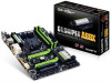
Step 2: Align the notch on your OP chip with the notch on the socket and gently press the chip into the socket until seated. For purchasing the IC extractor and OP Chip, please contact the local dealer. 1-9 Internal Connectors 1 3 4 2 4 4 9 15 13 5 5 7 8 11 12 10 14 6 5 1) ATX_12V 2) ATX 3) CPU_FAN 4) SYS_FAN1/SYS_FAN2/SYS_FAN3 5) SATA3 0/1/2/3/4/5/6/7 6) F_PANEL 7) F_AUDIO 8) SPDIF_O 9) F_USB30 10) F_USB1/F_USB2 11) COM 12) TPM 13) BAT 14) CLR_CMOS 15) CAP_SW1/CAP_SW2 Read the following guidelines before connecting external devices: •• First make sure your devices are compliant with the connectors you wish to connect. •• Before installing the devices, be sure to turn off the devices and your computer. Unplug the power cord from the power outlet to prevent damage to the devices. •• After installing the device and before turning on the computer, make sure the device cable has been securely attached to the connector on the motherboard. - 13 -
-
 1
1 -
2
-
3
-
4
-
5
-
6
-
7
-
 8
8 -
 9
9 -
 10
10 -
 11
11 -
 12
12 -
 13
13 -
 14
14 -
 15
15 -
 16
16 -
 17
17 -
 18
18 -
19
-
20
-
21
-
22
-
23
-
24
-
25
-
26
-
27
-
28
-
29
-
30
-
31
-
32
-
33
-
34
-
35
-
36
 |
 |
