Gigabyte GA-7PCSLN Manual - Page 10
Force to Stop FRB3 Timer jumper
 |
View all Gigabyte GA-7PCSLN manuals
Add to My Manuals
Save this manual to your list of manuals |
Page 10 highlights
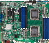
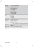
Item Code 1 ID_SW 2 MLAN 3 USB_LANB1 4 USB_LANB2 5 VGA_1 6 COM1 7 P12V_AUX2 8 ATX1 9 CPU1 10 DDR3_P0_C1 11 DDR3_P0_C0 12 DDR3_P0_A0 13 DDR3_P0_B0 14 CPU0 15 P12V_AUX1 16 BAT 17 SKU_KEY1 18 CPU0_FAN 19 SYS_FAN4 20 SYS_FAN3 21 SYS_FAN2 22 SYS_FAN1 23 SATA0/1 24 PMbus_CN_1 25 BP_1 26 SSB_ME2 27 SATA2/3/4/5 28 SATA_SGPIO 29 SCU_SGPIO 30 MINISAS_1 31 SAS0~3 32 F_USB1 33 FP_1 34 COM2 35 TPM_MEZZ1 36 PCI_1 37 ROMST_FRB3 38 PCIE_3 39 IPMB 40 BMC_LED1 41 PCIE_2 42 PCIE_1 43 CPU1_FAN 44 DDR3_P1_D0 45 DDR3_P1_E0 Description ID switch BMC Management LAN port LAN1 port (top) / USB ports (bottom) LAN2 port (top) / USB ports (bottom) VGA port Serial port 8 pin power connector 24-pin power connector Intel LGA1356 socket (Secondary CPU) Channel C slot 1 (for primary CPU) Channel C slot 0 (for primary CPU) Channel A slot 0 (for primary CPU) Channel B slot 0 (for primary CPU) Intel LGA1356 socket (Primary CPU) 8 pin power connector CMOS battery PBG A SKU Select connector CPU0 fan connector System fan connector System fan connector System fan connector System fan connector SATA 6Gb/s connectors PM Bus connector HDD back plane connector ME enable/disable jumper SATA 3Gb/s connectors SATA SGPIO coneector SCU SGPIO connector Mini SAS connector SAS connectors Front USB connector Front panel connector Serial cable connector TPM connector PCI slot (32bit/33MHz) Force to Stop FRB3 Timer jumper PCI-E slot 3 (x8 slot / x4 signal) IPMB connector BMC Firmware Readiness LED PCI-E slot 2 (x16 slot / x8 signal) PCI-E slot 1 (x16 slot) CPU1 fan connector Channel A slot 0 (for secondary CPU) Channel B slot 0 (for secondary CPU) - 10 -
-
 1
1 -
2
-
3
-
4
-
 5
5 -
 6
6 -
 7
7 -
 8
8 -
 9
9 -
 10
10 -
 11
11 -
 12
12 -
 13
13 -
 14
14 -
 15
15 -
16
-
17
-
18
-
19
-
20
-
21
-
22
-
23
-
24
-
25
-
26
-
27
-
28
-
29
-
30
-
31
-
32
-
33
-
34
-
35
-
36
-
37
-
38
-
39
-
40
-
41
-
42
-
43
-
44
-
45
-
46
-
47
-
48
-
49
-
50
-
51
-
52
-
53
-
54
-
55
-
56
-
57
-
58
-
59
-
60
-
61
-
62
-
63
-
64
-
65
-
66
-
67
-
68
-
69
-
70
-
71
-
72
-
73
-
74
-
75
-
76
-
77
-
78
-
79
-
80
-
81
-
82
-
83
-
84
-
85
-
86
-
87
-
88
-
89
-
90
-
91
 |
 |
