Gigabyte GA-7TESM Manual - Page 14
Installation Steps
 |
View all Gigabyte GA-7TESM manuals
Add to My Manuals
Save this manual to your list of manuals |
Page 14 highlights
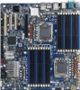
Hardware Installation Process Installation Steps: Step 1. Insert the DIMM memory module vertically into the DIMM slot, and push it down. Step 2. Close the plastic clip at both edges of the DIMM slots to lock the DIMM module. NOTE! DIMM must be populated in order starting from DIMMA1/D1 socket. For dual-channel operation, DIMMs must be installed in matched pairs. Step 3. Reverse the installation steps when you wish to remove the DIMM module. 1 2 2 DDR_P1C1D0 DDR_P1C1D1 DDR_P1C1D2 DDR_P0C1D2 DDR_P0C1D1 DDR_P0C1D0 CPU1 DDR_P1C2D0 DDDDRR__PP11CC22DD21 DDR_P1C0D0 DDR_DPD1RC_0PD12C0D1 CPU0 DDRD_DPR0_CPD00DDC0R0_DP10C0D2 DDDRDD_RPD_0RPC0_2CPD020CD21D2 14
-
 1
1 -
2
-
3
-
4
-
5
-
6
-
7
-
8
-
 9
9 -
 10
10 -
 11
11 -
 12
12 -
 13
13 -
 14
14 -
 15
15 -
 16
16 -
 17
17 -
 18
18 -
 19
19 -
20
-
21
-
22
-
23
-
24
-
25
-
26
-
27
-
28
-
29
-
30
-
31
-
32
-
33
-
34
-
35
-
36
-
37
-
38
-
39
-
40
-
41
-
42
-
43
-
44
-
45
-
46
-
47
-
48
-
49
-
50
-
51
-
52
-
53
-
54
-
55
-
56
-
57
-
58
-
59
-
60
-
61
-
62
-
63
-
64
-
65
-
66
-
67
-
68
-
69
-
70
-
71
 |
 |

14
Hardware Installation Process
Installation Steps:
Step 1.
Insert the DIMM memory
module vertically into the DIMM slot, and push it
down.
Step 2.
Close the plastic clip at both edges of the DIMM slots to lock the DIMM module.
NOTE!
DIMM must be populated in order starting from DIMMA1/D1 socket. For dual-channel
operation, DIMMs must be installed in matched pairs.
Step 3.
Reverse the installation steps when you wish to remove the DIMM module.
2
2
1
CPU1
CPU0
DDR_P1C0D2
DDR_P1C0D1
DDR_P1C0D0
DDR_P1C1D2
DDR_P1C1D1
DDR_P1C1D0
DDR_P1C2D2
DDR_P1C2D1
DDR_P1C2D0
DDR_P0C2D0
DDR_P0C2D1
DDR_P0C2D2
DDR_P0C0D0
DDR_P0C0D1
DDR_P0C0D2
DDR_P0C1D0
DDR_P0C1D1
DDR_P0C1D2