Gigabyte GA-8I915G Pro Manual - Page 22
PWR_LED, S_ATA1/S_ATA2/S_ATA3/S_ATA4Serial ATA Connector, Controlled by ICH6 - bios
 |
View all Gigabyte GA-8I915G Pro manuals
Add to My Manuals
Save this manual to your list of manuals |
Page 22 highlights
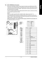
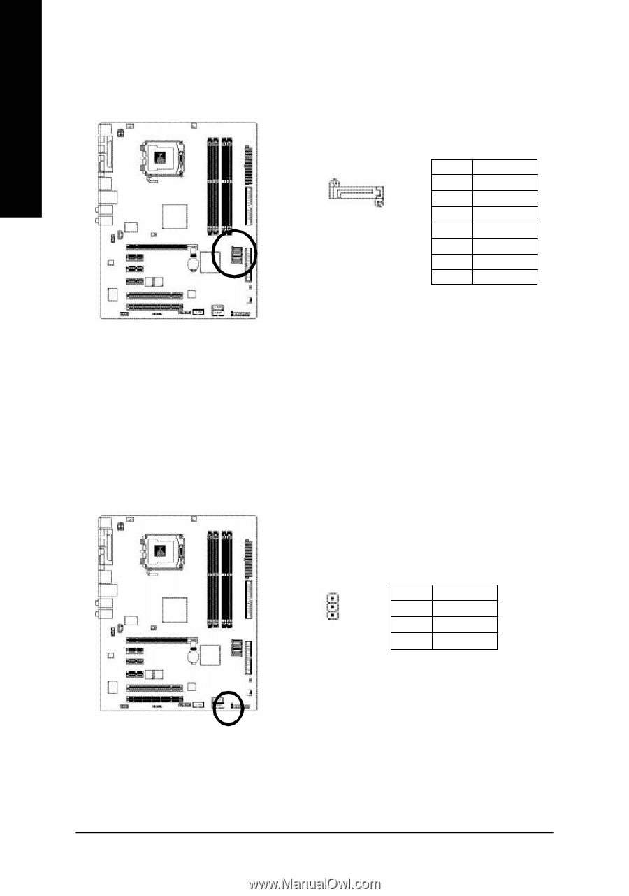
English 9) S_ATA1/S_ATA2/S_ATA3/S_ATA4(SerialATA Connector,Controlled by ICH6) Serial ATA can provide 150M B/s transfer r ate. Please refer to the BIOS setting for the Serial ATA and install the proper driver in order to work properly. 7 1 S_ATA (Control by ICH 6) Pin No. 1 2 3 4 5 6 7 Definition GND TXP TXN GND RXN RXP GND 10) PWR_LED PWR_LED is connect with the system power indicator to indicate whether the system is on/off. It will blink when the system enters suspend mode. Pin No. Definition 1 MPD+ 1 2 MPD- 3 MPD- GA-8I915G Pro Motherboard - 22 -
-
 1
1 -
2
-
3
-
4
-
5
-
6
-
7
-
8
-
9
-
10
-
11
-
12
-
13
-
14
-
15
-
16
-
 17
17 -
 18
18 -
 19
19 -
 20
20 -
 21
21 -
 22
22 -
 23
23 -
 24
24 -
 25
25 -
 26
26 -
 27
27 -
28
-
29
-
30
-
31
-
32
-
33
-
34
-
35
-
36
-
37
-
38
-
39
-
40
-
41
-
42
-
43
-
44
-
45
-
46
-
47
-
48
-
49
-
50
-
51
-
52
-
53
-
54
-
55
-
56
-
57
-
58
-
59
-
60
-
61
-
62
-
63
-
64
-
65
-
66
-
67
-
68
-
69
-
70
-
71
-
72
-
73
-
74
-
75
-
76
-
77
-
78
-
79
-
80
 |
 |
GA-8I915G Pro Motherboard
- 22 -
English
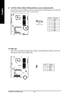
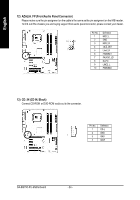
10) PWR_LED
PWR_LED is connect with the system power indicator to indicate whether the system is on/off. It will
blink when the system enters suspend mode.
1
Pin No.
Definition
1
MPD+
2
MPD-
3
MPD-
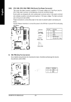
9)
S_ATA1/S_ATA2/S_ATA3/S_ATA4(Serial ATA Connector, Controlled by ICH6)
Serial ATA can provide 150MB/s transfer rate. Please refer to the BIOS setting for the Serial ATA
and install the proper driver in order to work properly.
Pin No.
Definition
1
GND
2
TXP
3
TXN
4
GND
5
RXN
6
RXP
7
GND
7
1
S_ATA
(Control by ICH 6)