Gigabyte GA-8I945PL-G Manual - Page 23
F_PANEL Front Panel Jumper, CD_IN CD
 |
View all Gigabyte GA-8I945PL-G manuals
Add to My Manuals
Save this manual to your list of manuals |
Page 23 highlights
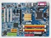
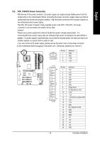
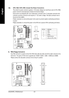
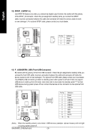
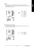
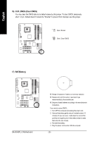
English 10) F_PANEL (Front Panel Jumper) Please connect the power LED, PC speaker, reset switch and power switch etc of your chassis front panel to the F_PANEL connector according to the pin assignment below. Message LED/ Power/ Sleep LED Speaker Connector Power Switch MSG+ MSG- PW+ PWSPEAK+ SPEAK- 2 20 1 19 HD+ HD- RESRES+ NC HD (IDE Hard Disk Active LED) (Blue) SPEAK (Speaker Connector) (Amber) RES (Reset Switch) (Green) PW (Power Switch) (Red) MSG(Message LED/Power/Sleep LED) (Yellow) NC ( Purple) Reset Switch IDE Hard Disk Active LED Pin 1: LED anode(+) Pin 2: LED cathode(-) Pin 1: Power Pin 2- Pin 3: NC Pin 4: Data(-) Open: Normal Close: Reset Hardware System Open: Normal Close: Power On/Off Pin 1: LED anode(+) Pin 2: LED cathode(-) NC 11) CD_IN (CD IN) Connect CD-ROM or DVD-ROM audio out to the connector. Pin No. Definition 1 CD-L 1 2 GND 3 GND 4 CD-R - 23 - Hardware Installation
-
 1
1 -
2
-
3
-
4
-
5
-
6
-
7
-
8
-
9
-
10
-
11
-
12
-
13
-
14
-
15
-
16
-
17
-
 18
18 -
 19
19 -
 20
20 -
 21
21 -
 22
22 -
 23
23 -
 24
24 -
 25
25 -
 26
26 -
 27
27 -
 28
28 -
29
-
30
-
31
-
32
-
33
-
34
-
35
-
36
-
37
-
38
-
39
-
40
-
41
-
42
-
43
-
44
-
45
-
46
-
47
-
48
-
49
-
50
-
51
-
52
-
53
-
54
-
55
-
56
-
57
-
58
-
59
-
60
-
61
-
62
-
63
-
64
-
65
-
66
-
67
-
68
-
69
-
70
-
71
-
72
-
73
-
74
-
75
-
76
-
77
-
78
-
79
-
80
 |
 |