Gigabyte GA-946GZ-DS3 Manual - Page 18
Connectors Introduction
 |
View all Gigabyte GA-946GZ-DS3 manuals
Add to My Manuals
Save this manual to your list of manuals |
Page 18 highlights
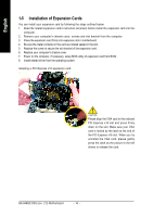
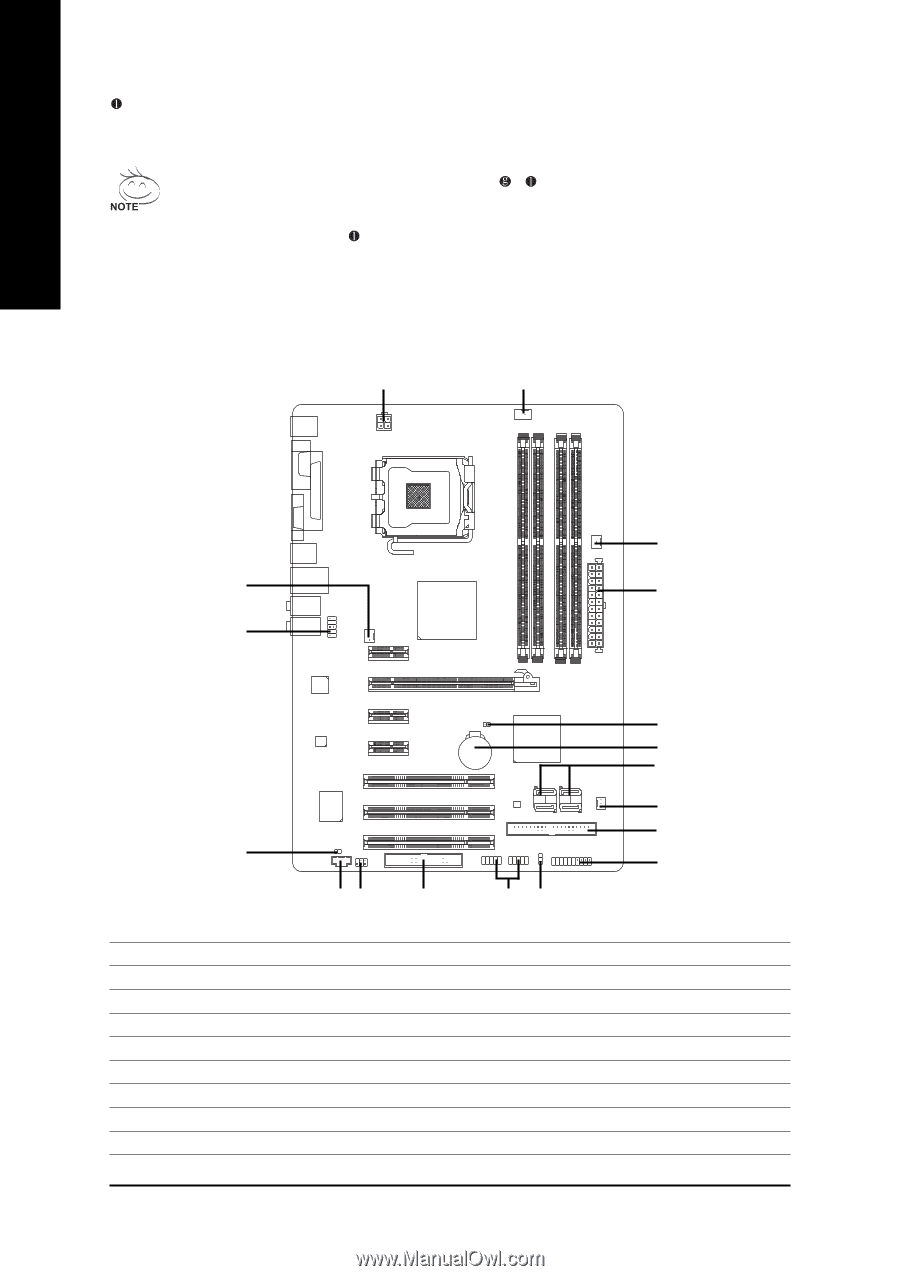
English MIC In The default MIC In jack. Microphone must be connected to MIC In jack. In addition to the default speakers settings, the ~ audio jacks can be reconfigured to perform different functions via the audio software. Only microphones still MUST be connected to the default Mic In jack ( ). Please refer to the 2-/4-/6-/8- channel audio setup steps for detailed software configuration information. 1-7 Connectors Introduction 1 3 5 6 2 11 16 13 14 1) ATX_12V 2) ATX (Power Connector) 3) CPU_FAN 4) SYS_FAN 5) PWR_FAN 6) NB_FAN 7) IDE1 8) FDD 9) SATAII0 / 1 / 2 / 3 GA-946GZ-DS3 (rev. 2.0) Motherboard 17 18 9 4 7 12 8 15 10 10) PWR_LED 11) F_AUDIO 12) F_PANEL 13) CD_IN 14) SPDIF_IO 15) F_USB1 / F_USB2 16) CI 17) CLR_CMOS 18) BATTERY - 18 -
-
 1
1 -
2
-
3
-
4
-
5
-
6
-
7
-
8
-
9
-
10
-
11
-
12
-
 13
13 -
 14
14 -
 15
15 -
 16
16 -
 17
17 -
 18
18 -
 19
19 -
 20
20 -
 21
21 -
 22
22 -
 23
23 -
24
-
25
-
26
-
27
-
28
-
29
-
30
-
31
-
32
-
33
-
34
-
35
-
36
-
37
-
38
-
39
-
40
-
41
-
42
-
43
-
44
-
45
-
46
-
47
-
48
-
49
-
50
-
51
-
52
-
53
-
54
-
55
-
56
-
57
-
58
-
59
-
60
-
61
-
62
-
63
-
64
-
65
-
66
-
67
-
68
-
69
-
70
-
71
-
72
-
73
-
74
-
75
-
76
-
77
-
78
-
79
-
80
 |
 |
GA-946GZ-DS3 (rev. 2.0) Motherboard
- 18 -
English
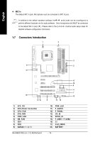
1-7
Connectors Introduction
1)
ATX_12V
2)
ATX (Power Connector)
3)
CPU_FAN
4)
SYS_FAN
5)
PWR_FAN
6)
NB_FAN
7)
IDE1
8)
FDD
9)
SATAII0 / 1 / 2 / 3
10)
PWR_LED
11)
F_AUDIO
12)
F_PANEL
13)
CD_IN
14)
SPDIF_IO
15)
F_USB1 / F_USB2
16)
CI
17)
CLR_CMOS
18)
BATTERY
1
2
3
10
15
18
16
14
17
13
12
5
6
4
11
9
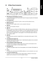
MIC In
The default MIC In jack. Microphone must be connected to MIC In jack.
In addition to the default speakers settings, the
~
audio jacks can be reconfigured to
perform different functions via the audio software.
Only microphones still MUST be connected
to the default Mic In jack (
). Please refer to the 2-/4-/6-/8- channel audio setup steps for
detailed software configuration information.
7
8