Gigabyte GA-B150M-D2V DDR3 User Manual - Page 18
F_USB1/F_USB2 USB 2.0/1.1 Headers, TPM Trusted Platform Module Header, COM Serial Port Header
 |
View all Gigabyte GA-B150M-D2V DDR3 manuals
Add to My Manuals
Save this manual to your list of manuals |
Page 18 highlights
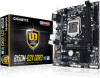
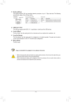
10) F_USB1/F_USB2 (USB 2.0/1.1 Headers) The headers conform to USB 2.0/1.1 specification. Each USB header can provide two USB ports via an optional USB bracket. For purchasing the optional USB bracket, please contact the local dealer. 9 1 10 2 Pin No. 1 2 3 4 5 Definition Power (5V) Power (5V) USB DXUSB DYUSB DX+ Pin No. 6 7 8 9 10 Definition USB DY+ GND GND No Pin NC G.QBOFM •• Do not plug the IEEE 1394 bracket (2x5-pin) cable into the USB 2.0/1.1 header. •• Prior to installing the USB bracket, be sure to turn off your computer and unplug the power cord from the power outlet to prevent damage to the USB bracket. DEBUG PORT 11) TPM (Trusted Platform Module Header) You may connect a TPM (Trusted Platform Module) to this header. Pin No. Definition Pin No. Definition 1 LCLK 11 LAD0 2 GND 12 GND 19 1 3 LFRAME 13 NC 4 No Pin 14 NC 20 2 5 LRESET 15 SB3V 6 NC 16 SERIRQ 7 LAD3 17 GND 8 LAD2 18 NC 9 VCC3 19 NC 10 LAD1 20 SUSCLK 12) COM (Serial Port Header) The COM header can provide one serial port via an optional COM port cable. For purchasing the optional COM port cable, please contact the local dealer. Pin No. Definition Pin No. Definition 1 NDCD- 6 NDSR- 9 1 10 2 2 NSIN 3 NSOUT 7 NRTS8 NCTS- 4 NDTR- 9 NRI- 5 GND 10 No Pin - 18 -
-
 1
1 -
2
-
3
-
4
-
5
-
6
-
7
-
8
-
9
-
10
-
11
-
12
-
 13
13 -
 14
14 -
 15
15 -
 16
16 -
 17
17 -
 18
18 -
 19
19 -
 20
20 -
 21
21 -
 22
22 -
 23
23 -
24
-
25
-
26
-
27
-
28
-
29
-
30
-
31
-
32
-
33
-
34
-
35
-
36
-
37
-
38
-
39
 |
 |
