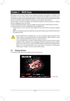
Gigabyte GA-B75M-D3H Manual - Page 22
CLR_CMOS Clear CMOS Jumper, TPM Trusted Platform Module Header - reset bios
 |
View all Gigabyte GA-B75M-D3H manuals
Add to My Manuals
Save this manual to your list of manuals |
Page 22 highlights
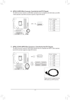
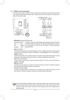
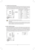
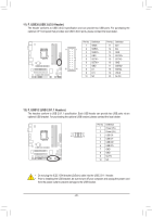
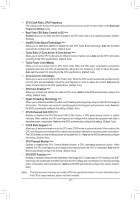
F_AUDIO(H) DB_PORT Voltage measurement module(X58A-O PCIe power connector (SATA)(X58 F_USB30 TPM w/housing 15) TPM (Trusted Platform Module Header) You may connect a TPM (Trusted Platform Module) to this header. 19 1 20 Pin No. 1 2 3 4 5 6 7 8 9 10 Definition LCLK GND LFRAME No Pin LRESET NC LAD3 LAD2 VCC3 LAD1 2 Pin No. 11 12 13 14 15 16 17 18 19 20 Definition LAD0 GND NC ID SB3V SERIRQ GND NC NC SUSCLK 16) CLR_CMOS (Clear CMOS Jumper) Use this jumper to clear the CMOS values (e.g. date information and BIOS configurations) and reset the CMOS values to factory defaults. To clear the CMOS values, use a metal object like a screwdriver to touch the two pins for a few seconds. Open: Normal Short: Clear CMOS Values •• Always turn off your computer and unplug the power cord from the power outlet before clearing the CMOS values. •• After system restart, go to BIOS Setup to load factory defaults (select Load Optimized Defaults) or manually configure the BIOS settings (refer to Chapter 2, "BIOS Setup," for BIOS configurations). - 22 -
-
 1
1 -
2
-
3
-
4
-
5
-
6
-
7
-
8
-
9
-
10
-
11
-
12
-
13
-
14
-
15
-
16
-
 17
17 -
 18
18 -
 19
19 -
 20
20 -
 21
21 -
 22
22 -
 23
23 -
 24
24 -
 25
25 -
 26
26 -
 27
27 -
28
-
29
-
30
-
31
-
32
-
33
-
34
-
35
-
36
-
37
-
38
-
39
-
40
-
41
-
42
-
43
-
44
 |
 |