Gigabyte GA-B85M-D3V User Manual - Page 15
F_PANEL Front Panel Header, CLR_CMOS Clear CMOS Jumper, SPEAK, PLED/PWR_LED
 |
View all Gigabyte GA-B85M-D3V manuals
Add to My Manuals
Save this manual to your list of manuals |
Page 15 highlights
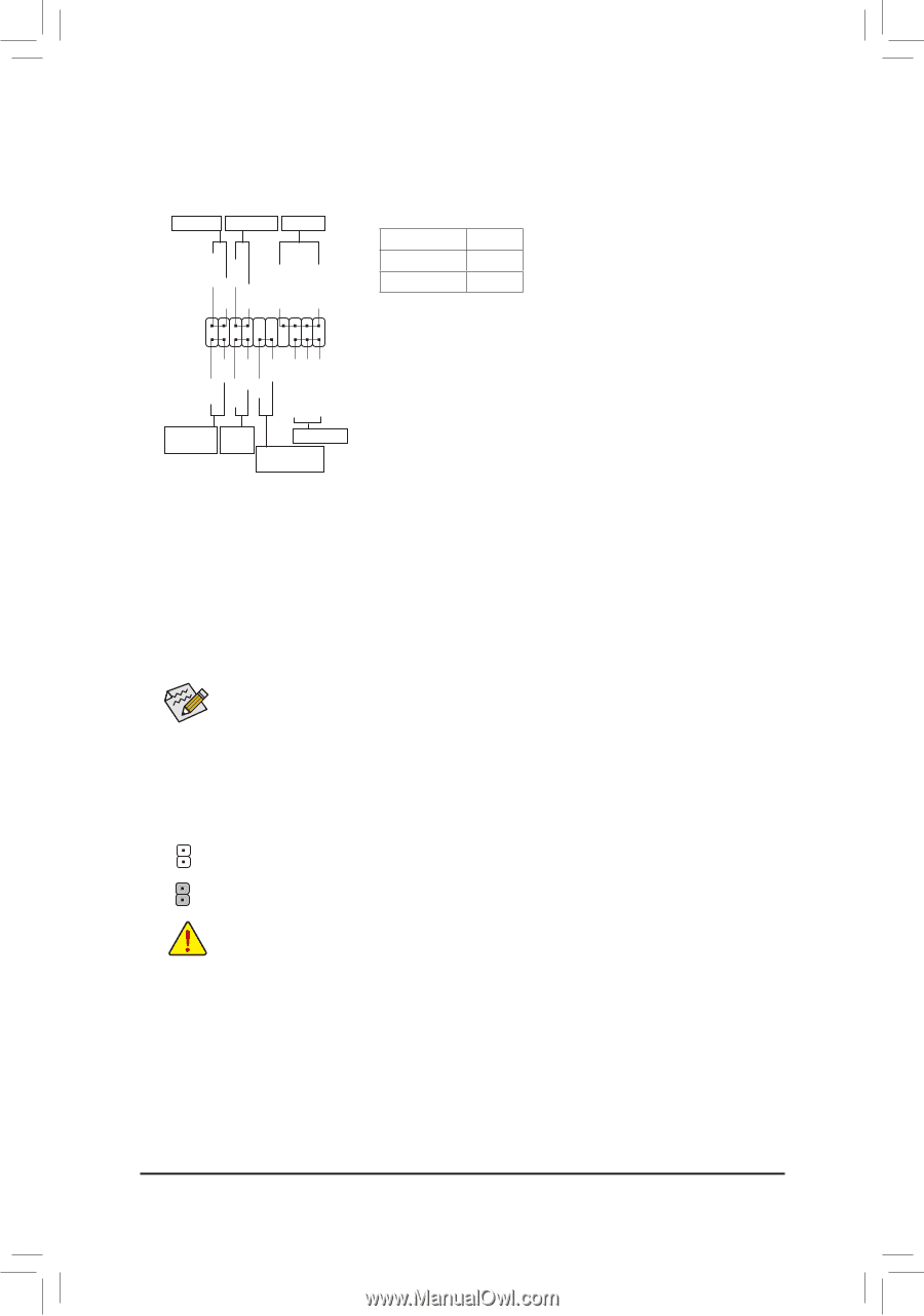
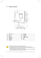
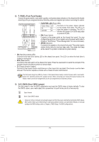
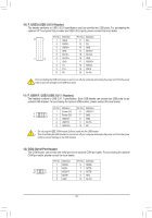
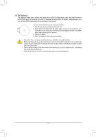
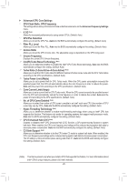
1 23 1 1 23 1 SS 1 S 1 23 U 1 23 1 8) F_PANEL (Front Panel Header) Connect the power switch, reset switch, speaker, and system status indicator on the chassis to this header according to the pin assignments below. Note the positive and negative pins before connecting the cables. Power LED Power Switch Speaker • PLED/PWR_LED (Power LED): System Status LED Connects to the power status indicator PLED+ PLED- PW+ PWSPEAK+ SPEAK- S0 On S3/S4/S5 Off on the chassis front panel. The LED is on when the system is operating. The LED is off when the system is in S3/S4 sleep state F_ 2 1 or powered off (S5). 20 • PW F(P_ ower Switch): SS U 123 19 Connects to the power switch on the chassis front panel. You may HD+ HD- RESRES+ CICI+ PWR_LED+ PWR_LEDPWR_LED- configure the way to turn off your system using the power switch (refer to Chapter 2, "BIOS Setup," "Power Management," for more information). • SPEAK (Speaker): Connects to the speaker on the chassis front panel. The system reports Hard Drive Reset Activity LED Switch Power LED Chassis Intrusion Header system startup status by issuing a beep code. One single short beep will be heard if no problem is detected at system startup. •• HD (Hard Drive Activity LED): Connects to the hard drive activity LED on the chassis front panel. The LED is on when the hard drive is reading or writing data. •• RES (Reset Switch): _S Connects to the reset switch on the chassis front panel. Press the reset switch to restart the computer if the computer freezes and fails to perform a normal restart. • CI (Chassis Intrusion Header): Connects to the chassis intrusion switch/sen_sor on the chassis that can detect if the chBasSs_is cover has been removed. This function requires a chassis witBh a chassis intrusion switch/sensor. B The front panel design may differ by chassis. A front panel module mainly consists of power switch, reset switch, power LED, hard drive activity LED, speaker and etc. When connecting your chassis front panel module to this header, make sure the wire assignments and the pin assignments are matched correctly. S B_ B 9) CLR_CMOS (Clear CMOS Jumper) Use this jumper to clear the BIOS configuration and reset the CMOS values to factory defaults. To clear the CMOS values, use a metal object like a screwdriver to touch the two pins for a few seconds. Open: Normal _S Short: Clear CMOS Values S_ _ B •• Always turn off your computer and unplug the power cord from the power outlet before clearing the CMOS values. •• After system restart, go to BIOS Setup to load factory defaults (select Load Optimized Defaults) or manually configure the BIOS settings (refer to_CUhapter 2, "BIOS Setup," for BIOS configurations). _ __ 3 B F_USB3 F - 15 -
-
 1
1 -
2
-
3
-
4
-
5
-
6
-
7
-
8
-
9
-
 10
10 -
 11
11 -
 12
12 -
 13
13 -
 14
14 -
 15
15 -
 16
16 -
 17
17 -
 18
18 -
 19
19 -
 20
20 -
21
-
22
-
23
-
24
-
25
-
26
-
27
-
28
-
29
-
30
-
31
-
32
-
33
-
34
-
35
-
36
 |
 |