Gigabyte GA-F2A68HM-DS2 User Manual - Page 14
SATA3 0/1/2/3 SATA 6Gb/s Connectors, F_PANEL Front Panel Header, SPDIF_O S/PDIF Out Header, RAID 1 - reset bios
 |
View all Gigabyte GA-F2A68HM-DS2 manuals
Add to My Manuals
Save this manual to your list of manuals |
Page 14 highlights
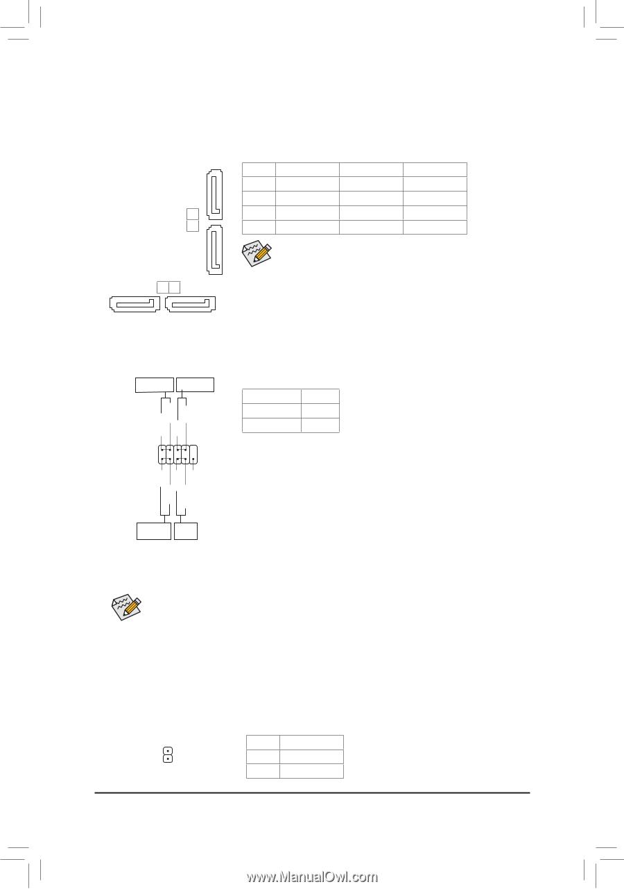
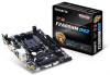
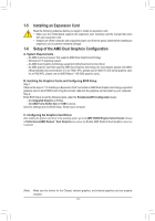
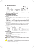
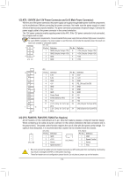
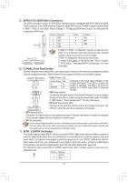
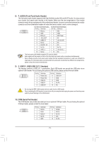
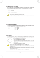
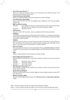
DEBUG PORT 5) SATA3 0/1/2/3 (SATA 6GDbE/sBUCGonnectDoErBsU)G The SATA connectors conforPmORtTo SATA 6GPbO/RsTstandard and are compatible with SATA 3Gb/s and SATA 1.5Gb/s standard. Each SATA connector supports a single SATA device. The AMD Chipset supports RAID 0, RAID 1, RAID 10, and JBOD. Refer to Chapter 3, "Configuring SATA Hard Drive(s)," for instructions on configuring a RAID array. 1 Pin No. Definition Pin No. Definition 1 GND 5 RXN 2 TXP 6 RXP SATA3 2 3 3 TXN 4 GND 7 GND •• A RAID 0 or RAID 1 configuration requires at least two hard drives. If more than two hard drives are to be used, the total number of hard drives must be an even number. SATA3 0 1 7 1 7 •• A RAID 10 configuration requires four hard drives. •• To enable hot-plugging for the SATA ports, refer to Chapter 2, "BIOS Setup," "Peripherals\SATA Configuration," for more information. 6) F_PANEL (Front Panel Header) Connect the power switch, reset switch, and system status indicator on the chassis to this header according to the pin assignments below. Note the positive and negative pins before connecting the cables. Power LED Power Switch PWPW+ PLED- PLED+ 2 10 1 9 •• PLED (Power LED): System Status LED S0 On S3/S4/S5 Off •• PW (Power Switch): Connects to the power status indicator on the chassis front panel. The LED is on when the system is operating. The LED is off when the system is in S3/S4 sleep state or powered off (S5). Connects to the power switch on the chassis front panel. You may configure NC RES+ RESHD- HD+ the way to turn off your system using the power switch (refer to Chapter 2, "BIOS Setup," "Power Management," for more information). •• HD (Hard Drive Activity LED): Connects to the hard drive activity LED on the chassis front panel. The Hard Drive Reset Activity LED Switch LED is on when the hard drive is reading or writing data. •• RES (Reset Switch): Connects to the reset switch on the chassis front panel. Press the reset switch to restart the computer if the computer freezes and fails to perform a normal restart. •• NC: No connection. The front panel design may differ by chassis. A front panel module mainly consists of power switch, reset switch, hard drive activity LED and etc. When connecting your chassis front panel module to this header, make sure the wire assignments and the pin assignments are matched correctly. 7) SPDIF_O (S/PDIF Out Header) This header supports digital S/PDIF Out and connects a S/PDIF digital audio cable (provided by expansion cards) for digital audio output from your motherboard to certain expansion cards like graphics cards and sound cards. For example, some graphics cards may require you to use a S/PDIF digital audio cable for digital audio output from your motherboard to your graphics card if you wish to connect an HDMI display to the graphics card and have digital audio output from the HDMI display at the same time. For information about connecting the S/PDIF digital audio cable, carefully read the manual for your expansion card. Pin No. Definition 1 SPDIFO 1 2 GND - 14 -
-
 1
1 -
2
-
3
-
4
-
5
-
6
-
7
-
8
-
 9
9 -
 10
10 -
 11
11 -
 12
12 -
 13
13 -
 14
14 -
 15
15 -
 16
16 -
 17
17 -
 18
18 -
 19
19 -
20
-
21
-
22
-
23
-
24
-
25
-
26
-
27
-
28
-
29
-
30
-
31
-
32
-
33
-
34
-
35
-
36
 |
 |