Gigabyte GA-F2A75-D3H User Manual - Page 24
CPU_FAN/SYS_FAN1/SYS_FAN2/SYS_FAN3 Fan Headers, CLR_CMOS Clear CMOS Jumper
 |
View all Gigabyte GA-F2A75-D3H manuals
Add to My Manuals
Save this manual to your list of manuals |
Page 24 highlights
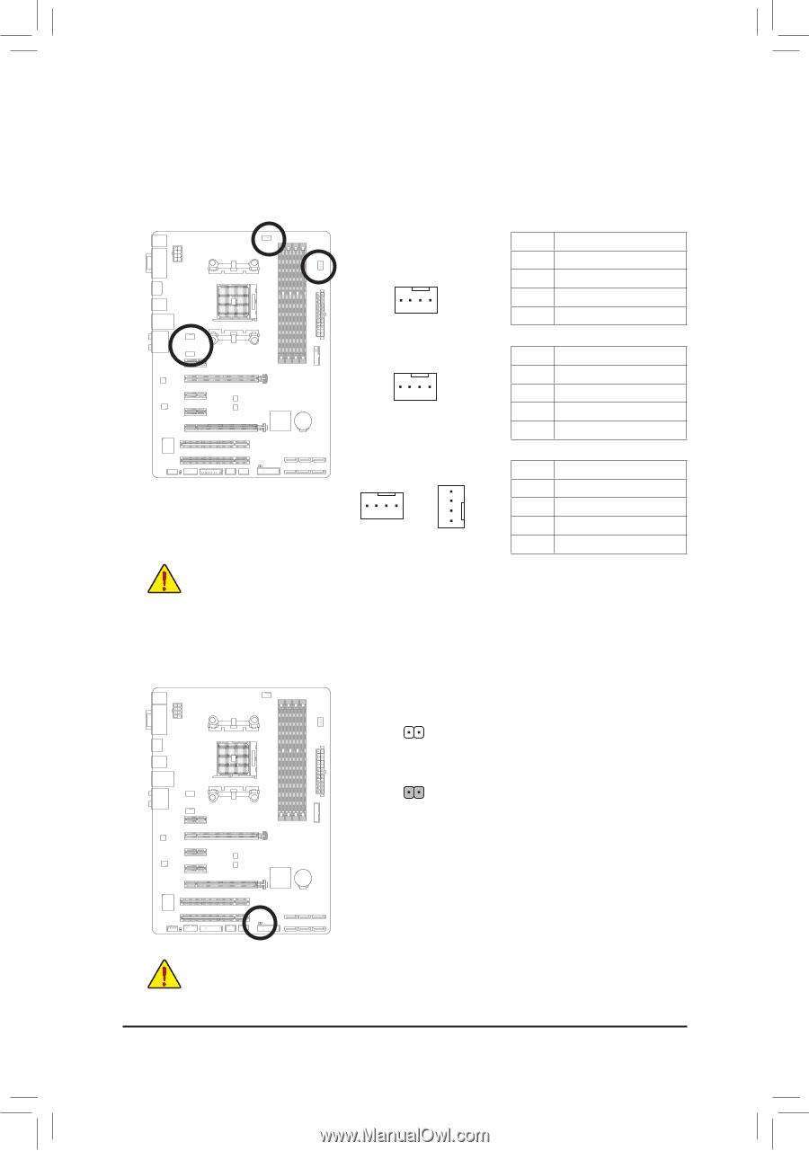
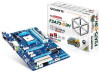
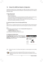
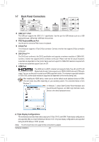
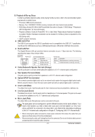
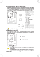
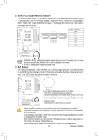
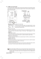
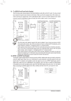
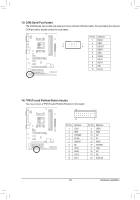
3/4) CPU_FAN/SYS_FAN1/SYS_FAN2/SYS_FAN3 (Fan Headers) All fan headers on this motherboard are 4-pin. Most fan headers possess a foolproof insertion design. When con- necting a fan cable, be sure to connect it in the correct orientation (the black connector wire is the ground wire). The motherboard supports APU fan speed control, which requires the use of a APU fan with fan speed control design. For optimum heat dissipation, it is recommended that a system fan be installed inside the chassis. CPU_FAN: Pin No. Definition 1 GND 2 +12V /Speed Control 1 CPU_FAN 3 Sense 4 Speed Control SYS_FAN1: Pin No. Definition 1 GND 1 2 +12V/Speed Control SYS_FAN1 3 Sense 4 Reserve SYS_FAN2/SYS_FAN3: Pin No. Definition 1 SYS_FAN2 1 SYS_FAN3 1 GND 2 +12V 3 Sense 4 Speed Control •• Be sure to connect fan cables to the fan headers to prevent your APU and system from overheating. Overheating may result in damage to the APU or the system may hang. •• These fan headers are not configuration jumper blocks. Do not place a jumper cap on the headers. 5) CLR_CMOS (Clear CMOS Jumper) Use this jumper to clear the CMOS values (e.g. date information and BIOS configurations) and reset the CMOS values to factory defaults. To clear the CMOS values, use a metal object like a screwdriver to touch the two pins for a few seconds. Open: Normal Short: Clear CMOS Values •• Always turn off your computer and unplug the power cord from the power outlet before clearing the CMOS values. •• After system restart, go to BIOS Setup to load factory defaults (select Load Optimized Defaults) or manually configure the BIOS settings (refer to Chapter 2, "BIOS Setup," for BIOS configurations). Hardware Installation - 24 -
-
 1
1 -
2
-
3
-
4
-
5
-
6
-
7
-
8
-
9
-
10
-
11
-
12
-
13
-
14
-
15
-
16
-
17
-
18
-
 19
19 -
 20
20 -
 21
21 -
 22
22 -
 23
23 -
 24
24 -
 25
25 -
 26
26 -
 27
27 -
 28
28 -
 29
29 -
30
-
31
-
32
-
33
-
34
-
35
-
36
-
37
-
38
-
39
-
40
-
41
-
42
-
43
-
44
-
45
-
46
-
47
-
48
-
49
-
50
-
51
-
52
-
53
-
54
-
55
-
56
-
57
-
58
-
59
-
60
-
61
-
62
-
63
-
64
-
65
-
66
-
67
-
68
-
69
-
70
-
71
-
72
-
73
-
74
-
75
-
76
-
77
-
78
-
79
-
80
-
81
-
82
-
83
-
84
-
85
-
86
-
87
-
88
-
89
-
90
-
91
-
92
-
93
-
94
-
95
-
96
 |
 |